Iveco Stralis AT/AD. Manual - part 323


  Index      Iveco     Iveco Stralis AT/AD - service repair manual 2003 year


Search            


Content   ..  321  322  323  324   ..


Iveco Stralis AT/AD. Manual - part 323


74601

74602

1)

Turn the key to START.

2)

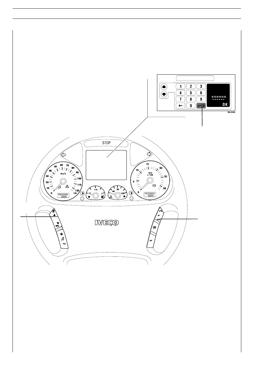
The display shown in the figure appears.

3)

Select the first digit of the ELECTRONIC CODE with push buttons ARROW UP and ARROW DOWN (A).

4)

Confirm the digit selected with OK (C).

5)

Continue with the remaining digits of the ELECTRONIC CODE.

6)

When the entire ELECTRONIC CODE is entered, select (B) and confirm with OK (C).

IMMOBILIZER

ENTER

CODE

press

B

C

A

III.76

ELECTRONIC SYSTEMS

S

TRALIS

AT/AD

Base - January 2003

It enables engine start when the key cannot be recognised or the IMMOBILIZER centre is down. Entering the electronic
code shown on the CODE CARD and operating the steering wheel push buttons can start the engine.

The MS6.2 electronic center manages the following main functions:

Fuel injection
Accessory functions such as cruise control, speed limiter, PTO and the like
Turbine geometry variations
Engine brake cut-it
Self-diagnosis
Recovery

It also enables:

Interfacing with other on-board electronic systems
Diagnosis

Fuel dosing

Fuel dosing is calculated based on:
-

accelerator pedal position

-

engine rpm

-

quantity of air admitted.

The result can be corrected based on:
-

water temperature

or to prevent:
-

noise

-

fumes

-

overloads

-

overheating

-

turbine over rpm

Pressure can be adjusted in case of:
-

engine brake actuation

-

actuation of external devices such as ASR, speed limiter and the like

-

serious defects involving load reduction or engine stop.

After determining the mass of air introduced by measuring its volume and temperature, the center calculates in mg per delivery
the corresponding mass of fuel to be injected into the cylinder involved, with account also taken of gas oil temperature.
The mass of fuel thus calculated is first transformed into volume (in mm

3

per delivery) and then in flywheel degrees, that is to say

injection duration.

Delivery correction based on water temperature

When cold, the engine encounters greater operating resistance, mechanical friction is high, oil is till very viscous and operating plays
are not optimized yet.
Fuel injected also tends to condense on cold metal surfaces.
Fuel dosing with a cold engine is therefore greater than when hot.

Delivery correction to prevent noise, fumes or overloads

Behaviors that could lead to the defects under review are well known, so the designer has added specific instructions to the center
to prevent them.

De-rating

In the event of engine overheating, decreasing delivery proportionally to the temperature reached by the coolant changes injection.

Turbine rpm adjustment

Turbine speed is adjusted continuously and corrected by acting on geometry, if so required.

ELECTRONIC SYSTEMS

III.77

S

TRALIS

AT/AD

EDC
Engine management - EDC System

Injection lead electronic control

Injection lead, or the start of fuel delivery expressed in degrees, can differ from one injection to the next, even from one cylinder
to another and is calculated similarly to delivery according to engine load, namely, accelerator position, engine rpm and air admitted.
Lead is corrected as required:
-

during acceleration

-

according to water temperature

and to obtain:
-

reduced emissions, noise abatement and no overload

-

better vehicle acceleration

High injection lead is set at start, based on water temperature.
Delivery start feedback is given by injection electro valve impedance variation.

Speed adjuster

The electronic speed adjuster features both regulator characteristics:
-

minimum and maximum

-

all rpm levels

It remains stable in ranges where conventional mechanical adjusters become imprecise.

Engine start

Cylinder 1 step and recognition signal synchronization (flywheel and drive shaft sensors) takes place at first engine turns. Accelerator
pedal signal is ignored at start. Star delivery is set exclusively based on water temperature, via a specific map. The center enables
the accelerator pedal, when it detects flywheel acceleration and rpm such as to consider the engine as started and no longer drawn
by the starter motor.

Cold start

Pre-post reheating is activated when even only one of the three water, air or gas oil temperature sensors records a temperature
of below 10 _C. The pre-heat warning light goes on when the ignition key is inserted and stays on for a variable period of time
according to temperature, while the intake duct input resistor heats the air, then starts blinking, at which point the engine can be
started.
The warning light switches off with the engine revving, while the resistor continues being fed for a variable period of time to complete
post-heating. The operation is cancelled to avoid uselessly discharging the batteries if the engine is not started within 20

÷ 25 seconds

with the warning light blinking. The pre-heat curve is also variable based on battery voltage.

Hot start

On inserting the ignition key the warning light goes on for some 2 seconds for a short test and then switches off when all reference
temperatures are above 10 _C. The engine can be started at this point.

Run Up

When the ignition key is inserted, the center transfers data stored at previous engine stop to the main memory (Cf. After run), and
diagnoses the system.

After Run

At each engine stop with the ignition key, the center still remains fed by the main relay for a few seconds, to enable the micropro-
cessor to transfer some data from the main volatile memory to an non-volatile, cancelable and rewritable (Eeprom) memory to
make tem available for the next start (Cf. Run Up).
These data essentially consists of:
-

miscellaneous settings, such as engine idling and the like

-

settings of some components

-

breakdown memory

The process lasts for some seconds, typically from 2 to 7 according to the amount of data to be stored, after which the ECU sends
a command to the main relay and makes it disconnect from the battery.

III.78

ELECTRONIC SYSTEMS

S

TRALIS

AT/AD

Base - January 2003

Cut-off

This is the delivery cutout function during deceleration, engine braking and the like.

Cylinder Balancing

Individual cylinder balancing contributes to increasing comfort and operability.
This function enables individual personalized fuel delivery control and delivery start for each cylinder, even differently between each
cylinder, to compensate for injector hydraulic tolerances.
Delivery flow differences between the various injectors cannot be assessed directly by the center, this information being supplied
by entering the code for each injector via the Modus.

Synchronization search

The center can anyhow recognize the cylinder to inject fuel into even in the absence of a signal from the camshaft sensor.

If this occurs when the engine is already started, combustion sequence is already acquired, so the center continues with the sequence

it is already synchronized on; if it occurs with the engine stopped, the center only actuates one electro valve. Injection occurs onside
that cylinder within 2 shaft revs at the utmost so the center is only required to synchronize on the firing sequence and start the engine.

The center is mounted directly on the engine via a heat exchanger to enable cooling via elastic pads that minimize engine-induced
vibration, to reduce the number of connections, the length of cables connecting with the injectors and all disturbances to the signal
transmitted.

It is connected to the vehicle via two 35-pole connectors:
connector “A” for components present on the engine
connector “B” for cab components.

An internal environment pressure sensor is provided for further improved injection system management.

The center is provided with an advanced self-diagnosis system capable of identifying and storing any intermittent environmental
anomaly to the system during vehicle operation to ensure the most correct and efficient repair.

This procedure must never be interrupted, by cutting the engine off from the battery cutout or disconnecting the latter before 10
seconds at least after engine cutout.

In this case, system operation is guaranteed until the fifth improper engine cutout, after which an error is stored in the breakdown
memory and the engine operates at lower performance at next start while the EDC warning light stays on.

Repeated procedure interruptions could in fact lead to center damage.

ELECTRONIC SYSTEMS

III.79

S

TRALIS

AT/AD


Content   ..  321  322  323  324   ..