Iveco Stralis AT/AD. Manual - part 271
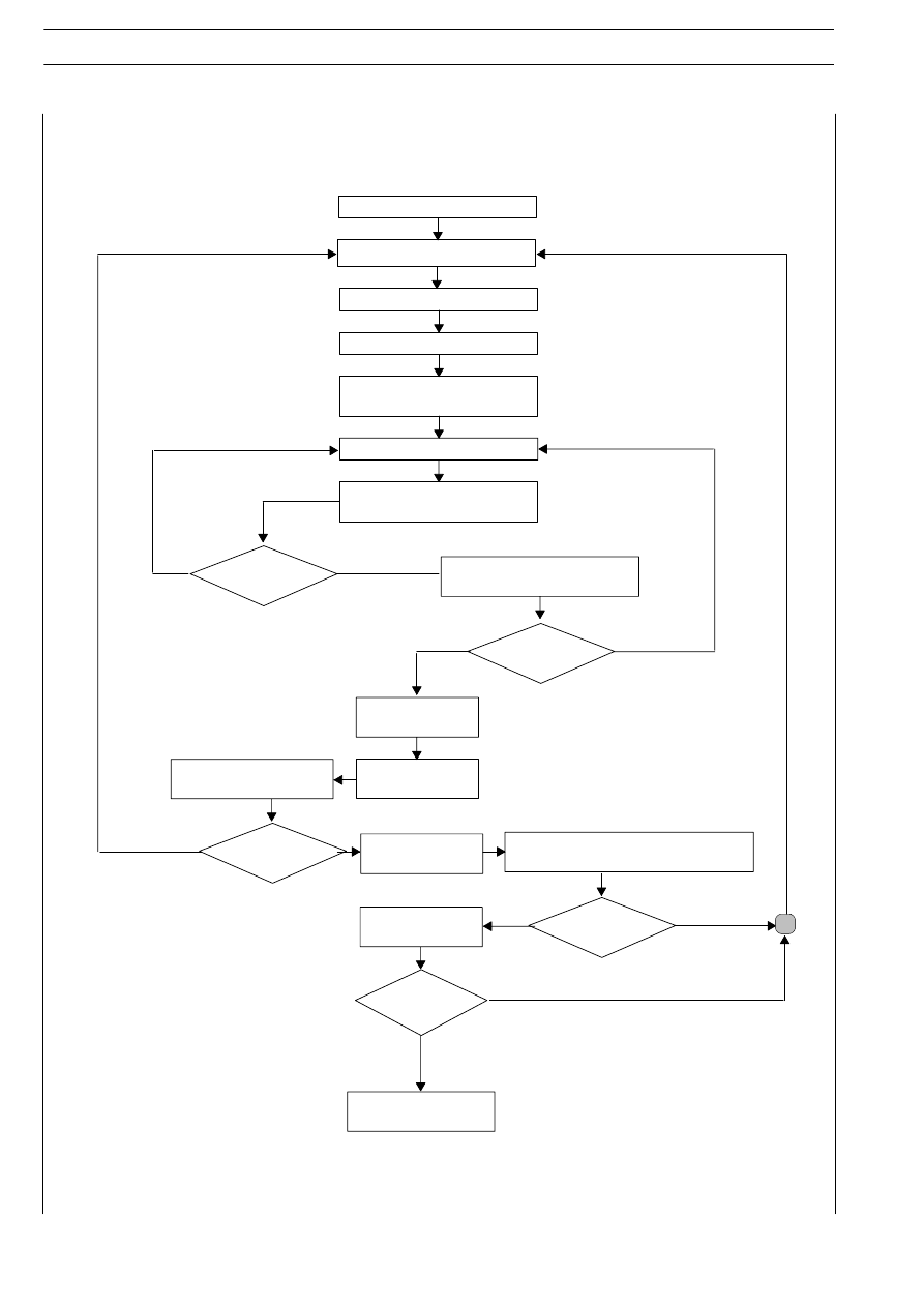
Drain off oil
from the system
Preparing the station
First recovery
Wait 3-5 minutes
Second recovery
Operate on the system
Vacuum for 5-10 minutes
with first vacuum test
Vacuum for 30 minutes
with second vacuum test
Load oil
into the system
Load up to 200 g
refrigerant
Search for leakage with
electronic leak finder
Fully load
the system
Search system for leakage with
electronic leak finder
Pressure check
Are the values
acceptable?
Disconnect the station
from the system
NO
NO
YES
YES
NO
NO
YES
YES
YES
NO
Is there any
leakage?
Is there any
leakage?
Is there any
leakage?
Is there any
leakage?
18
BODYWORK AND CHASSIS FRAME
S
TRALIS
AT/AD
Base - January 2003