Iveco Stralis AT/AD. Manual - part 270


  Index      Iveco     Iveco Stralis AT/AD - service repair manual 2003 year


Search            


Content   ..  268  269  270  271   ..


Iveco Stralis AT/AD. Manual - part 270


PROCEDURE FOR EMPTYING AND
REFILLING THE AIR-CONDITIONING
SYSTEMS WITH R134A REFRIGERANT
R134A refrigerant recovery and refilling station
(99305146)

This station has been made to be used on all air-conditioning/
heating systems for motor vehicles using R134A gas.

By connecting the station to a refrigerating system the gas it
contains can be recovered, cleaned and made ready to be
reloaded into the system or be transferred to an external
container. In addition, it is possible to see the amount of oil
taken from the system, restore it and ”empty” the system.

To be operative, the station needs to absorb approximately 3
kg of refrigerant.

For prompt use it is advised to have at least 2 kg of refrigerant
in the filler cylinders and to keep the station as level as possible.

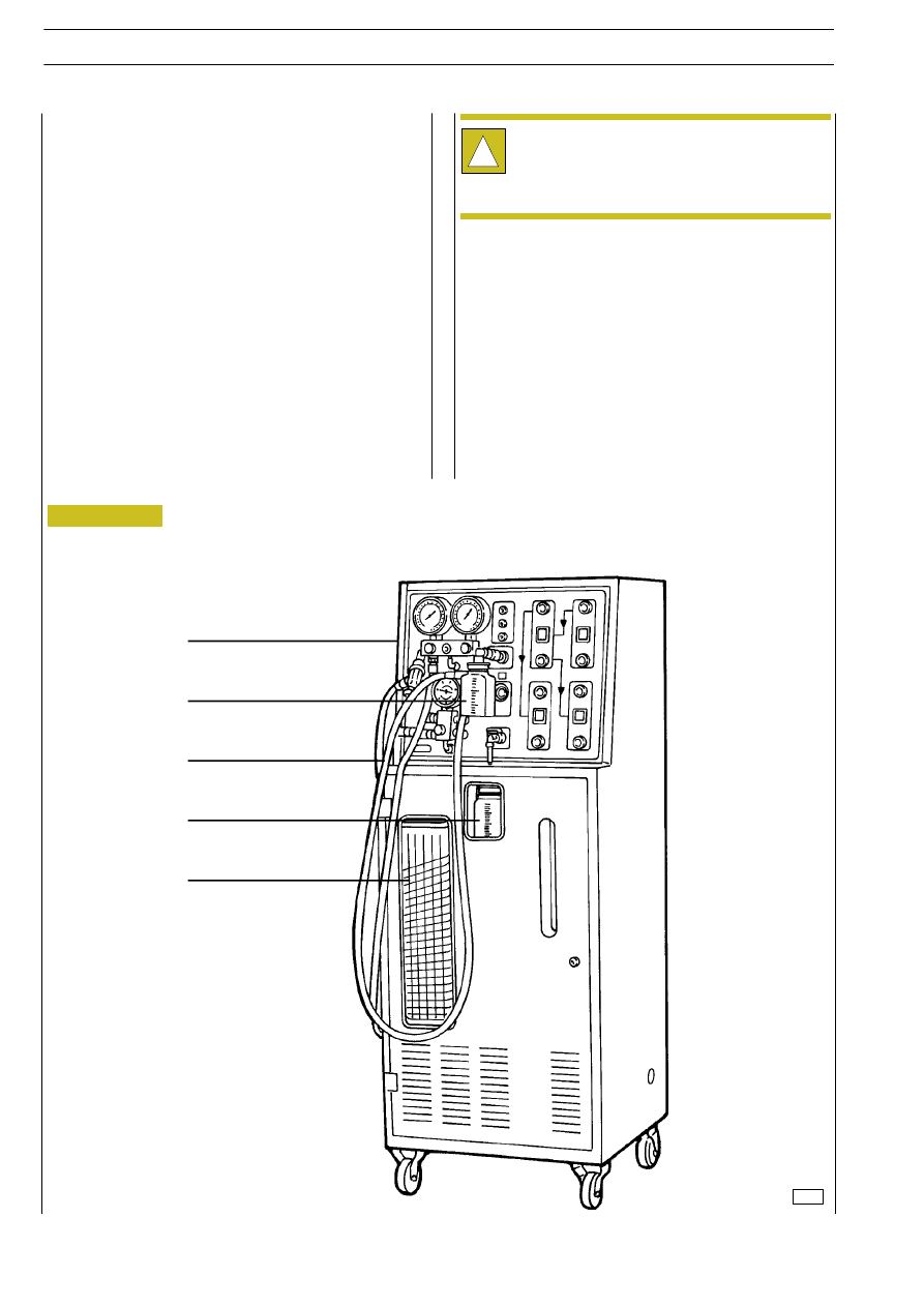
The station is composed of:

1

control panel;

2

container to restore any oil recovered when unloading;

3

flexible hoses;

4

container to collect any oil recovered from the system;

5

filler cylinder with graduated scale revolving.

Figure 17

1

2

3

4

5

50631

This procedure does not describe the phases of loading
and unloading refrigerant to and from external and
internal containers or maintenance. Therefore, please
refer to the operating and maintenance manual of the
appliance.

!

14

BODYWORK AND CHASSIS FRAME

S

TRALIS

AT/AD

Base - January 2003

- never expose the unit or operate it in acidic or wet

environments or close to open containers of inflammable
substances;

- the unit must operate in places with good ventilation;

- never alter the settings of the safety valves and control

systems;

- never use bottles or other storage containers that are not

approved and are not fitted with safety valves;

- never load any container over 80% of its maximum

capacity;

- never leave the unit powered if it is not to be used

immediately. Cut off the mains power supply when it is
not planned to use the equipment.

SAFETY STANDARDS

- always wear gloves and goggles when working with

refrigerant gases. Contact of refrigerant liquid with the
eyes can cause blindness;

- avoid all contact with skin (low boiling point -30

°C can

cause frostbite);

- never inhale the vapours of refrigerant gases;

- before connecting the station with a system or external

container, check that all the valves are closed;

- before disconnecting the station, check that the cycle is

over and all the valves are closed. This will prevent
dispersing refrigerant gas into the atmosphere;

The station is equipped with special fittings to avoid
contamination with systems using R12. Do not attempt to
adapt this unit for use with R12.

This station is exclusively for professionally trained
operators who must be familiar with refrigerating
systems, refrigerant gases and the damage pressurized
equipment can cause, therefore:

!

BODYWORK AND CHASSIS FRAME

15

S

TRALIS

AT/AD

FILLER CYLINDER

OIL TANK

Figure 18

Figure 19

50634

50632

16

BODYWORK AND CHASSIS FRAME

S

TRALIS

AT/AD

Base - January 2003

M1

Low pressure gauge

M2

High pressure gauge

M3

Filler cylinder pressure gauge

LOW Low-pressure valve

HIGH High-pressure valve

REF

Refrigerant filler and drain valve

V1

Valve on low-pressure pipe

V2

Valve on high-pressure pipe

V3

Oil injection valve for A/C system

V5

Oil drainage valve

V9

A/C system washing refrigerant service valve

10

Moisture indicator

VS

Safety and drainage valve

L3

Alarm warning light

L4

Maximum level warning light

L5

Minimum level warning light

A

Unit process / bottle heater switch

LA1

Unit process indicator light

LA2

Bottle heater indicator light

B

Refrigerant process / vacuum process switch

LB1

Refrigerant process indicator light

LB2

Vacuum process indicator light

C

Recovery recycle cycle / Filling switch

LC1

Recovery recycle cycle indicator light

LC2

Filling indicator light

D

Vacuum / vacuum test switch

LD1

Vacuum indicator light

LD2

Vacuum test indicator light

Control fascia diagram legend

Filler cylinder legend
1 Pressure values in bar (vertical lines, revolving top

cylinder).

2 Weight of load in grams (oblique lines, revolving top

cylinder) 50 g division between lines.

3 Tank level viewer (internal cylinder).

BODYWORK AND CHASSIS FRAME

17

S

TRALIS

AT/AD


Content   ..  268  269  270  271   ..