Iveco Stralis AT/AD. Manual - part 139
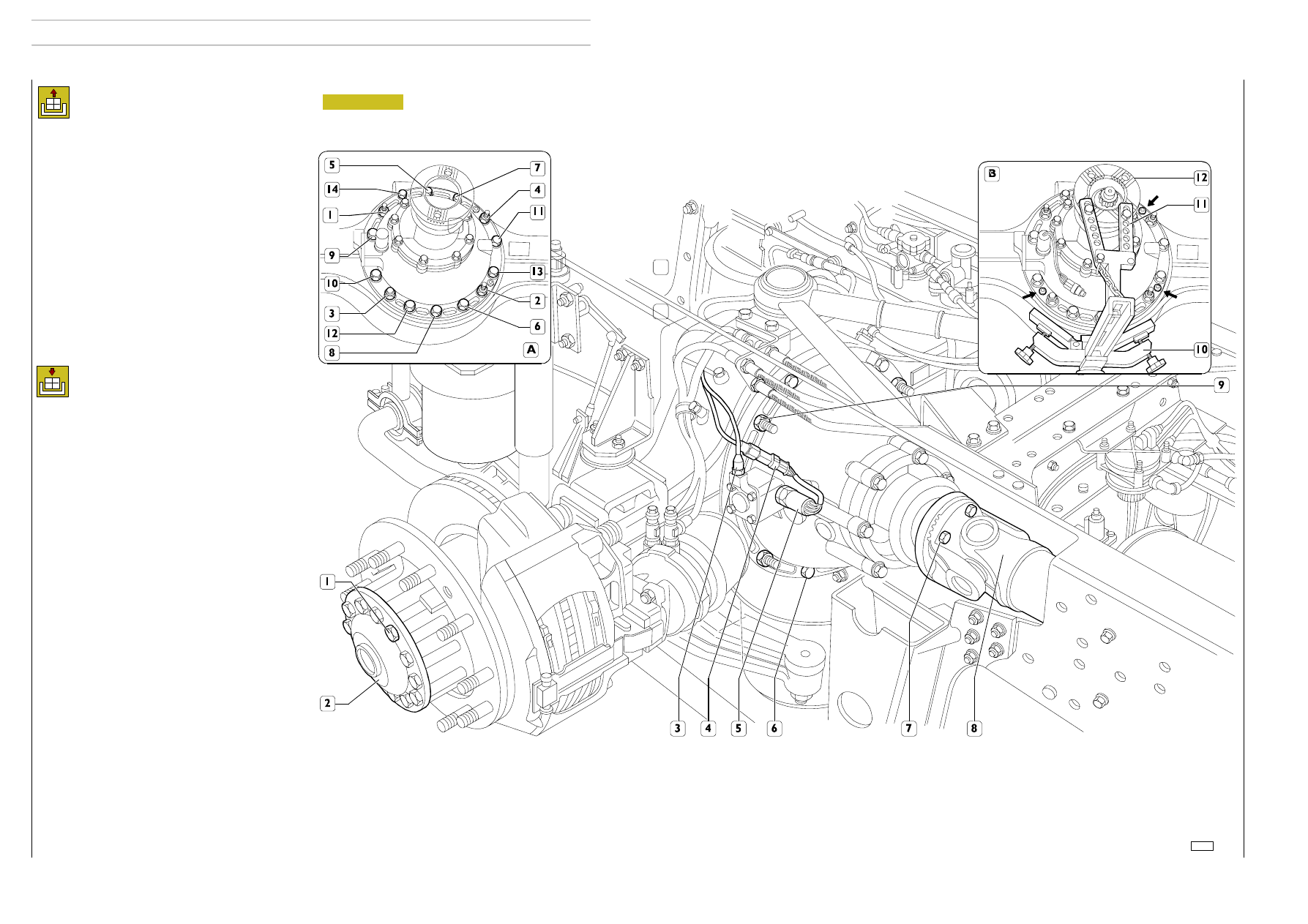
Figure 2
- Set the vehicle on level ground and lock the front wheels.
- Drain the oil from the axle housing through the drain
plug.
- Take out the screws (7) and disconnect the propeller
shaft (8) from the differential flange.
- Secure the propeller shaft to the vehicle’s chassis frame
with an appropriate rope.
- Disconnect the electrical connection (4) for the switch
(5) signalling differential locking and the air pipe (3) from
the differential locking control device.
- Disconnect the screws (1) fixing the drive shafts (2) and
extract them from the axle housing.
- Using the hydraulic jack, put the mount 993770616 (10,
det. B) under the differential and constrain the brackets
(11) of this mount to the flange (12) of the differential
sleeve (det. B).
- Unscrew the screws (6) and nuts (9) fixing the differen-
tial assembly to the axle housing.
- Remove the plugs (' det. B) from the threaded holes and
screw appropriate screws into them so as to extract the
differential from the axle housing.
72797
Removal
Refitting
For refitting, carry out the operations described for removal
in reverse order, keeping to the following instructions:
- The self-locking nuts have to be replaced with new parts
for each removal.
- After thoroughly cleaning the parts, apply sealant paste
onto the threads of the screws fixing the differential case
and the drive shafts.
- Tightening sequence diagram (differential case to axle
housing) (det. A)
1 — 2 — 3 — 4 nuts;
10 — 9 — 14 — 5 — 7 — 11 — 13 — 6 — 8 — 12 screws.
- Tighten the screws and nuts fixing the differential case
to the rear axle at the required torque and in the se-
quence indicated in the diagram.
After refitting:
- Screw the drain plug on and restore the level of oil with
the required quantity and grade.
- Check there is no leakage from the air pipe of the differ-
ential locking device and that it engages.
- Check that the differential locking indicator light in the
cab works correctly; if it does not, keep to the instruc-
tions described in the relevant section.
Instructions to adjust and check the operation of the trans-
mitter controlling differential locking and divider engagement.
The operation of the transmitter (two-function type) to con-
trol differential and divider engagement is adjusted and
checked with the axle mounted on the vehicle and proceed-
ing as described below:
- With differential locking, screw down the transmitter to
close the contacts and check the indicator light in the cab
comes on.
- The moment the indicator light in the cab comes on,
screw down the transmitter one more turn.
- Tighten the lock nut to lock the transmitter at a torque
of 40 Nm (4 kgm).
- Release the divider and differential locking engagement
control and check that the contacts are closed (in this
condition, the indicator light in the cab must be off).
6
REAR AXLES
S
TRALIS
AT/AD
Base - January 2003