Iveco Daily. Manual - part 426


  Index      Iveco     Iveco Daily - service repair manual 2004 year


Search            


Content   ..  424  425  426  427   ..


Iveco Daily. Manual - part 426


230

ELECTRIC/ELECTRONIC SYSTEM

D

AILY

Base - May 2004

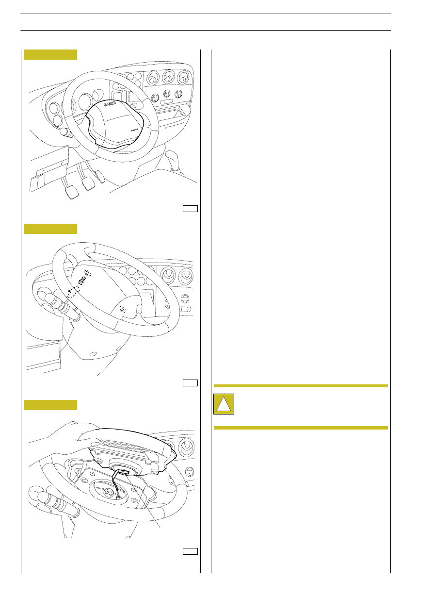
The module is at the centre of the steering wheel.
It mainly comprises the following:
- a bag inflation device, containing the triggering device and

the explosive charge

- a synthetic fibre bag, folded in a special wrapping
- a  plastic  cover  which  at  the  centre  and  sides  has

pre-established splitting lines which allow the bag out.

- A plate that fastens the module to the steering wheel

with two screws

Inflation of the bag takes place through the pre-established

controlled  expansion  of  the  volume  of  inert  harmless  gas

(ARGON), contained in a special module, after the heating

caused by a charge of solid propellant.
The rear part of the bag has suitably-sized holes which deflate

the bag immediately after inflation.
To remove the air bag module, proceed as follows:
- follow the rules of safety
- disconnect  the  battery  cables  (firstly  the  negative  one

then the positive) and isolate them taping the terminals;

- wait at least ten minutes before proceeding;
- slacken the two screws in the rear part of the steering

wheel;  to  gain  access  to each screw, turn the steering

wheel to be able to always work from the part of the

upper steering column cover;

- lift the module enough to disconnect the connector in its

centre;

- remove the module from the steering wheel.

AIR BAG MODULE

AIR BAG MODULE FASTENING SCREWS

AIR BAG MODULE REMOVAL

A. Connector

A

!

After removal undeployed air bags must be stored

in  a  special,  key-lockable  cabinet  with  the  plate

rested on the shelf.

Figure 264

Figure 265

Figure 266

8557

8558

8559

ELECTRIC/ELECTRONIC SYSTEM

231

D

AILY

Clock spring

The clock spring is a device fitted on the stalk unit ensuring

electrical continuity between the driver's module and the air

bag cable; it is formed of a container from which two cables

lead. One is connected to the air bag cable and one to the

driver's module. The container is composed of two overlaid

plates; the lower one is fastened to the stalk unit by three

screws and the upper one is made integral with the steering

wheel through two appendixes on its upper section.
Inside the two plates, the connection cables are wound in a

coil to be able to allow the cables to follow the movements

of the steering wheel, The clock spring also has a mechanism

that automatically prevents it from turning when it is removed

from the steering wheel; this consists in preventing the upper

plate,  no  longer  restrained,  from  turning  freely  causing

unwinding  or  winding  of  the  cables,  with  the  possibility  of

breakage.
When  the  steering  wheel  is  assembled  the  device  locks

automatically.
To remove the clock spring, proceed as follows:
- remove the driver's air bag module as described on the

previous page

- align  the  wheels  and  keep  them  in  this  position

throughout the whole operation

- slacken  the  nut  fastening  the  steering  wheel  to  the

steering column

- still with the wheels aligned, mark the position between

the steering wheel hub and the steering column

- remove the steering wheel taking care not to withdraw

the clock spring cable

REMOVING THE STEERING WHEEL FASTENING

NUTS

REFERENCE BETWEEN STEERING WHEEL HUB AND

STEERING COLUMN

REMOVING THE STEERING WHEEL

!

Make sure that removing the steering wheel cause

the upper plate of the clock spring to raise. If the

upper  plate  turns,  it  must  be  locked  taking  it

outwards; a click will be heard during locking.

Figure 267

Figure 268

Figure 269

8562

8561

8560

232

ELECTRIC/ELECTRONIC SYSTEM

D

AILY

Base - May 2004

the three fastening screws (Figure 270)

- working from inside, remove the upper steering column

half cover slackening the two fastening screws

- cut the strap that fastens the clock spring cable to the

steering  column  and  disconnect  the  connector  of  this

cable from the air bag cable

- slacken the three screws fastening the clock spring to the

stalk unit and remove it.

To refit the clock spring, proceed as follows:
- make sure the wheels are aligned
- if replacement of the clock spring is not necessary, refit

it,  after  removing  the  adhesive  tape  or  strap  put  on

previously,  without  making  the  upper  plate  turn,  then

tighten the three fastening screws

- in the case of fitting a new clock device, after fastening it

to the stalk unit, tear the plastic tab to lock the upper plate

and check that it does not turn

- connect the air bag cable connector to the clock spring

cable and fasten the latter to the steering column using

a suitable clamp

- assemble the two steering column halves fastening them

on the support plate with their screws

- carefully insert the cable to be connected to the driver's

air bag module through the slot provided on the steering

wheel hub

- assemble the steering wheel making the reference marks

made previously coincide.

- Tighten the steering wheel fastening nut to the specified

torque.

REMOVING THE STEERING COLUMN COVER HALVES

REMOVING THE CLOCK SPRING

CLOCK SPRING

!

Do  not  re-use  the  steering  wheel  fastening  nut

removed previously, replace it with a new one and

caulk it.

If the stalk unit is changed it must be replaced by

one inclusive of the clock spring.

NOTE

!

It is necessary to remove the clock spring without

making it turn, holding the upper plate in place with

a strap or adhesive tape.

Figure 270

Figure 271

Figure 272

8565

8564

8563

ELECTRIC/ELECTRONIC SYSTEM

233

D

AILY

Passenger's air bag module

This module is fitted on the dashboard and it is fastened on

the body by a special bracket; the operating principle is the

same as for the driver's module, only the size of the bag differs,

as it has to protect two people.
To remove the air bag module, proceed as follows:
- follow the rules of safety
- disconnect  the  battery  cables  (firstly  the  negative  one

then the positive) and isolate them taping the terminals

- wait at least ten minutes before proceeding
- slacken the two screws fastening the dashboard cover
- remove  the  dashboard  cover  in  such  a  way  as  to

overcome the resistance of the snap button in the lower

part of the cover

- disconnect the module cable connector from the air bag

cable

- slacken the four screws two on either side, that fasten the

module support bracket to the body and remove it.

PASSENGER'S AIR BAG MODULE

REMOVING THE DASHBOARD COVER

REMOVING THE AIR BAG MODULE

If the passenger's air bag is not fitted as it is optional,

a specific resistance is fitted on the connector during

production to simulate the charge

(R = 2.15 Ohm ± 0.35)

NOTE

8553

Figure 273

Figure 274

Figure 275

8554

8555


Content   ..  424  425  426  427   ..