Iveco Daily. Manual - part 425
226
ELECTRIC/ELECTRONIC SYSTEM
D
AILY
Base - May 2004
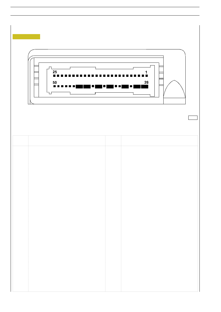
Pin
Function
Pin
Function
1
Positive for driver's pretensioner
26
Driver's pretensioner short circuit
2
Negative for driver's pretensioner
27
Driver's pretensioner short circuit
3
Positive for passenger's pretensioner
28
Passenger's pretensioner short circuit
4
Negative for passenger's pretensioner
29
Passenger's pretensioner short circuit
5
Key-operated positive supply
30
Ċ
6
Earth
31
Earth short circuit
7
Ċ
32
Short circuit
8
Ċ
33
Ċ
9
Line k for diagnostics
34
Ċ
10
Positive for driver's bag
35
Driver's bag short circuit
11
Negative for driver's bag
36
Driver's bag short circuit
12
Ċ
37
Ċ
13
Positive for passenger's bag
38
Passenger's bag short circuit
14
Negative for passenger's bag
39
Passenger's bag short circuit
15
Ċ
40
Failure warning light
16
Positive for centre pretensioner
41
Centre pretensioner short circuit
17
Negative for centre pretensioner
42
Centre pretensioner short circuit
18
Ċ
43
Ċ
19
Ċ
44
Ċ
20
Ċ
45
Ċ
21
Ċ
46
Ċ
22
Ċ
47
Ċ
23
Ċ
48
Ċ
24
Earth for diagnostics
49
Ċ
25
Ċ
50
Ċ
Figure 260
000283t