Iveco Daily. Manual - part 318


  Index      Iveco     Iveco Daily - service repair manual 2004 year


Search            


Content   ..  316  317  318  319   ..


Iveco Daily. Manual - part 318


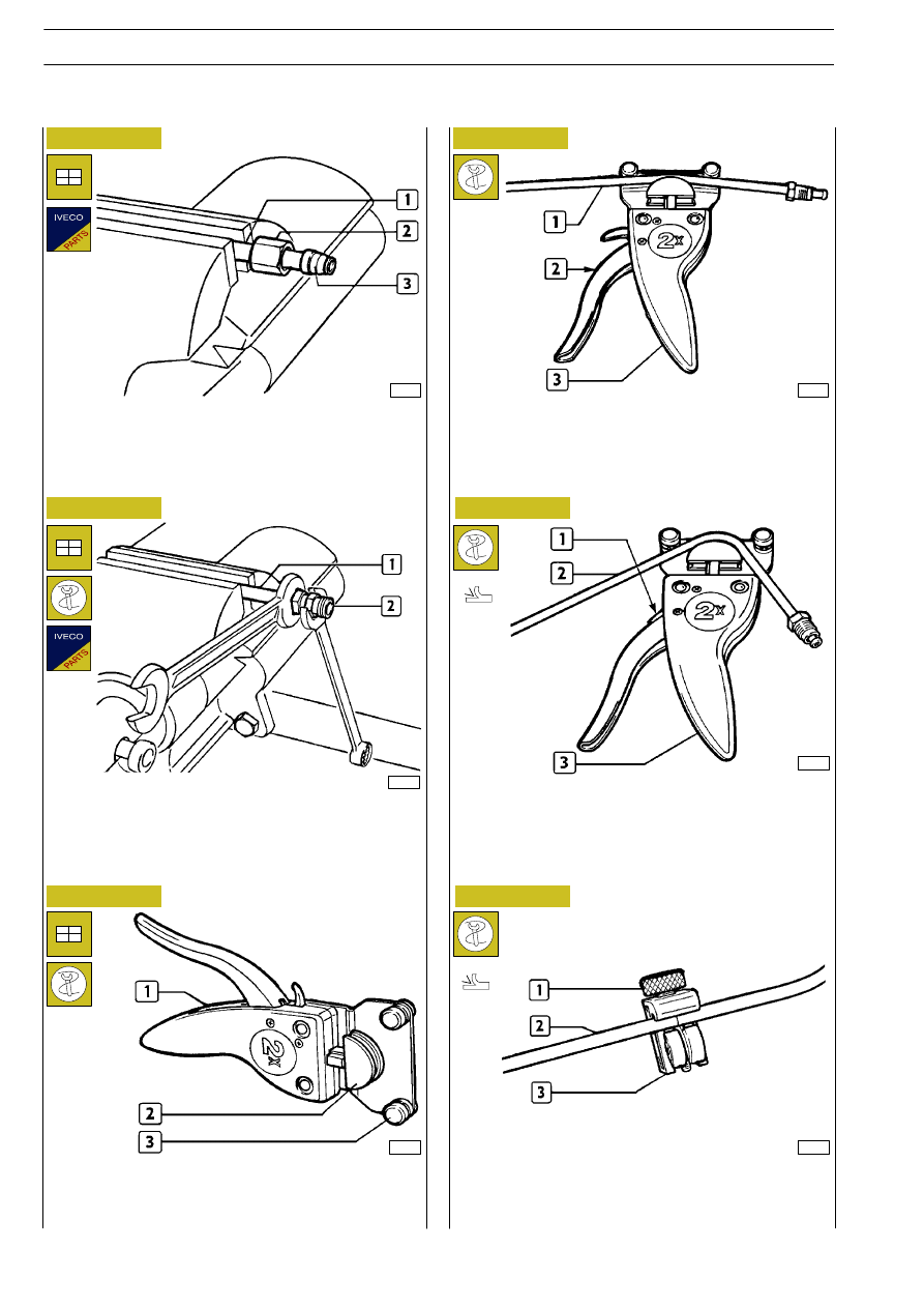
Fit union fitting (2) and tighten so that ring (3, Figure 6) is locked
over the pipe (1).

Bending rigid pipes

C type re-flanging

31979

Fit nut (2) and ring (3) over the pipe (1).

Position pipe (1) in tool (3) and bend the pipe by acting on lever
(2).

31976

31977

31980

To remove the pipe (2) from the tool (3) use lever (1).

31978

31981

Fit tool (1) 99386523 and select components (2) and (3)
according to the diameter of the pipe to be bent.

Position pipe (2) in tool (3) 99386523 and tighten screw (1).
By holding the pipe (2) still, rotate the tool (3) until the pipe
has been completely cut.

Cutting rigid pipes

Figure 6

Figure 7

Figure 8

Figure 9

Figure 10

Figure 11

18

HYDRO-PNEUMATIC SYSTEM - BRAKES

D

AILY

Base - May 2004

When the hose is incorrectly fitted, do not reuse the
hose once the bush and support ring have been
removed.

- Re-flange the support ring when fitted on the vehicle or

at the test bench on a union fitting.

- The pressure and the final distance of the pressure ring

front edge from the reinforcement bush should be in
accordance with those shown in the table below.

- only use type approved hoses;

- check the condition of the new hose, that must be free

from cracks, cuts or scores;

- cut the hose at 90

°, with respect the to axis, to the required

length by means of pipe-cutter pliers 99387050;

Fit the following in the specified order over the hose:

- nut (3), pressure ring (2) (the thickest part should be facing

the nut (3)) and the reinforcement bush (1);

- the bush must be in perfect condition (it must be free from

deformation or hammer dents).

Replacing

flexible

hoses

with

threaded

couplings

By turning tool (3) around the pipe (2), screw (1)
becomes loose. To completely cut the pipe, you must
tighten the screw (1) as soon as it becomes loose.

1. Reinforcement bush - 2. Pressure ring - 3. Nut -

4. Union fitting - 5. Hose - h. Distance between bush edge

and ring edge (see table)

Twin-layer

Carefully follow the instructions below:

10397

10398

10399

- Fit the reinforcement bush with tool 99372219 ensuring

contact between its flange and end of the hose.

- Make sure that the end of the hose penetrates into the

rake throat of the flange.

After having cut the pipe, deburr and shape the ends as
described previously.

ASSEMBLY OF REINFORCEMENT BUSH

A = CORRECT ASSEMBLY

B = INCORRECT ASSEMBLY

Hose

mm

Distance between

bush edge and ring

edge mm (*)

Fitting

pressure

(N/mm

2

)

6 x 1

8 x 1

10 x 1.5

12 x 1.6

16 x 2.34

0.040

0.050

0.050

0.060

0.060

Introduce the end of the prepared hose into the union fitting
until the reinforcement bush flange rests in the appropriate
seat:

- to lock the nut on the union fitting, tighten this up by hand

and then by means of a box wrench and dynamometric
wrench; this must tightened up to the required driving
torque.

Single layer

(*) See reference h, Figure 14.

Figure 12

Figure 13

Figure 14

da 1 a 1.5

da 2 a 2.5

da 2 a 2.5

da 2 a 2.5

da 3 a 3.5

NOTE

NOTE

HYDRO-PNEUMATIC SYSTEM - BRAKES

19

D

AILY

Base - May 2004

- check that the seal ring (1) is in its seal;

- tighten the coupling until the seal gasket is in contact with

the valve;

- direct the valve correctly and, by keeping the moveable

part still, lock the hexagonal nut to the driving torque
indicated in the table.

For greater safety and convenience in working, it is
advisable to remove the hoses during these
operations.

- Protect the hoses if grinding or welding operations are

carried out on the vehicle; a notice is fitted in the cabin
indicating the precautions to be observed to avoid
damage.

- when hoses run through chassis members or metal parts,

make sure that the holes through which they pass are
fitted with rubber grommets, and that these are in good
condition;

- avoid sliding the hose along sharp edges which might

cause cuts;

- when the hose has to be attached to existing pipe work,

take into account of the additional heat to which it may
be subjected (power steering pipe work). In this case the
hose must be protected with shields;

- when the hose has been connected, check that it is not

under tension between the attachment points, instead
leaving it slightly slack to take up the more substantial
variations in temperature, especially for short lengths;

- before fitting, thoroughly clean the hoses by blowing

compressed air through them to safeguard operation of
the system.

When fitting the hose to the vehicle, some important points
should be borne in mind:
- bends must comply with minimum radii, so as to avoid

constrictions;

Make sure that the hoses are not in contact with sharp
edges or with sharp metal parts or sources of heat,
but are at a minimum safe distance of 15mm from
these.

Figure 15

Replacing flexible hoses with quick release
couplings

When fitting is finished, check that all seals (unions, couplings,
etc.) are completely free from leaks.

Minimum radius of curvature

mm

Diameter of pipe

mm

13132

6 x 1

8 x 1

10 x 1.5

12 x 1.6

16 x 2.34

∼ 40

∼ 50

∼ 60

∼ 75

∼ 100

screw the coupling into the threaded seating provided on the
air valve, and tighten it to the driving torque indicated in the
table.

39307

Figure 16

Figure 17

39306

Swivel couplings:

Banjo couplings:

Swivel and banjo couplings:

COUPLING

DRIVING TORQUE (Nm + 10%)

THREAD

M 10 x 1.0 mm

M 12 x 1.5 mm

M 14 x 1.5 mm

M 16 x 1.5 mm

M 22 x 1.5 mm

22

24

28

35

40

!

!

1

20

HYDRO-PNEUMATIC SYSTEM - BRAKES

D

AILY

Base - May 2004

Whenever a hose is removed from a quick release
coupling, the coupling itself must be replaced. Spare
quick release couplings are supplied complete.

L

1

and L

2

vary according to the diameter of the hose

and are to be measured at the longer part of the hose
(see Figure 18).

- use indelible ink to clearly mark two reference notches on

both diametrically opposite faces of the pipe at an angle
of

≥ 75°, set to distances L

1

and L

2

, to ensure correct

fitting in place.

- only use type approved hoses;

- check the condition of the new hose, that must be free

from cracks, cuts or scores;

- cut the hose at 90

°, maximum error 15°, with reference

to the axis. Use pipe-cutter pliers 99387050 to cut to the
required length;

When removing couplings (1) on pneumatic components, check
the condition of the seal ring (2) and, if necessary, replace.

- Insert the hose (2) by hand into the coupling (1), with a

force between 30 and 120 N according to the diameter
of the hose, so that reference mark L

1

is inside the hose

while mark L

2

remains visible.

D

(mm)

33977

33978

6

8

12

16

Figure 18

Figure 19

Figure 20

33976

A

A = Mark to identify end of tube travel

19.8

20.5

25

27.1

17

18

22

24

22

23

28

30

L

(mm)

L

1

(mm)

L

2

(mm)

+0,5

0

+1

-0,5

+1

-0,5

Figure 21

39308

COUPLING

SEAL RING DIMENSIONS

THREAD

M 10 x 1.0

M 12 x 1.5

M 14 x 1.5

M 16 x 1.5

M 22 x 1.5

10.1 x 1.6

11.0 x 2.0

-

15.0 x 2.0

-

!

!

Quick release and threaded couplings are not
interchangeable. This also applies to flexible hoses
used with quick release couplings and flexible hoses
used with threaded couplings.

NOTE

HYDRO-PNEUMATIC SYSTEM - BRAKES

21

D

AILY

Base - May 2004


Content   ..  316  317  318  319   ..