Infiniti G35 (V35). Manual - part 471


  Index      Infiniti     Infiniti G35 (V35) Coupe - service repair manual 2007 year


Search            


Content   ..  469  470  471  472   ..


Infiniti G35 (V35). Manual - part 471


FUEL INJECTOR AND FUEL TUBE

EM-39

C

D

E

F

G

H

I

J

K

L

M

A

EM

3.

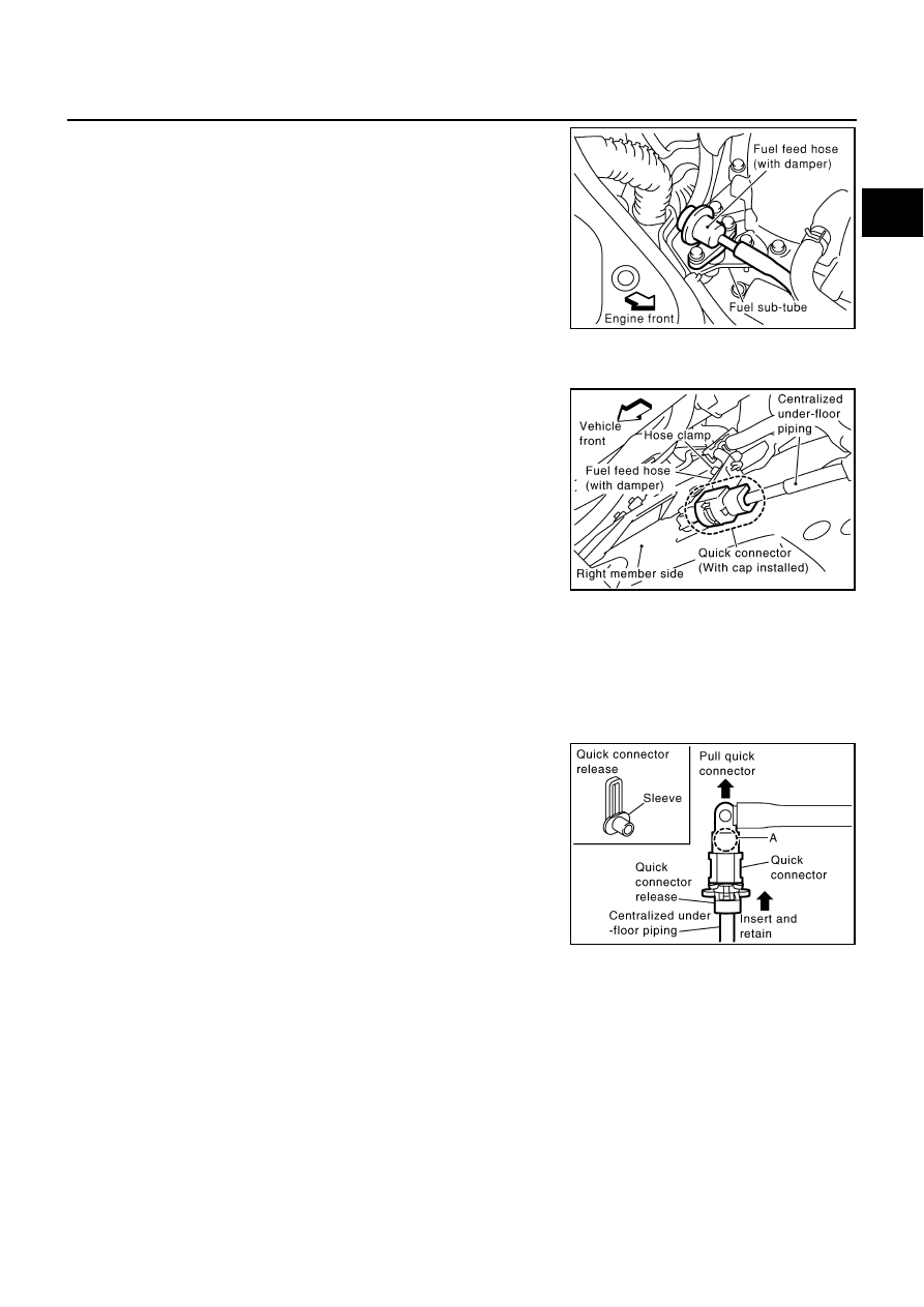
Remove fuel feed hose (with damper) from fuel sub-tube.

NOTE:
There is no fuel return route.

CAUTION:

While hoses are disconnected, plug them to prevent fuel
from draining.

Do not separate fuel damper and fuel feed hose.

4.

When separating fuel feed hose (with damper) and centralized under-floor piping connection, disconnect
quick connector as follows:

a.

Remove quick connector cap from quick connector connection
on right member side.

b.

Disconnect fuel feed hose (with damper) from bracket hose
clamp.

c.

Disconnect quick connector from centralized under-floor piping as follows:

CAUTION:

Disconnect quick connector by using quick connector release [SST: — (J-45488)], not by picking
out retainer tabs.

i.

With the sleeve side of quick connector release facing quick connector, install quick connector release
onto fuel tube.

ii.

Insert quick connector release into quick connector until sleeve
contacts and goes no further. Hold quick  connector release  on
that position.

CAUTION:

Inserting quick connector release hard will not disconnect
quick connector. Hold quick connector release where it
contacts and goes no further.

iii.

Draw and pull out quick connector straight from centralized
under-floor piping.

CAUTION:

Pull quick connector holding “A” position as shown in
the figure.

Do not pull with lateral force applied. O-ring inside quick connector may be damaged.

Prepare container and cloth beforehand as fuel will leak out.

Avoid fire and sparks.

Keep parts away from heat source. Especially, be careful when welding is performed around
them.

Do not expose parts to battery electrolyte or other acids.

Do not bend or twist connection between quick connector and fuel hose (with damper) during
installation/removal.

KBIA1293E

PBIC2083E

PBIC1898E

EM-40

FUEL INJECTOR AND FUEL TUBE

To keep clean the connecting portion and to avoid dam-
age and foreign materials, cover them completely with
plastic bags or something similar.

5.

Remove intake manifold collectors (upper and lower). Refer to 

EM-18, "INTAKE MANIFOLD COLLEC-

TOR"

 .

6.

Disconnect harness connector from fuel injector.

7.

Loosen mounting bolts in reverse order as shown in the figure,
and remove fuel tube and fuel injector assembly.

CAUTION:

Do not tilt it, or remaining fuel in pipes may flow out from
pipes.

8.

Remove spacers on intake manifold.

9.

Remove fuel injector from fuel tube as follows:

a.

Open and remove clip.

b.

Remove fuel injector from fuel tube by pulling straight.

CAUTION:

Be careful with remaining fuel that may go out from fuel
tube.

Be careful not to damage injector nozzles during
removal.

Do not bump or drop fuel injectors.

Do not disassemble fuel injectors.

10. Remove fuel sub-tube and fuel damper.

INSTALLATION

1.

Install fuel damper and fuel sub-tube.

When handling O-rings, be careful of the following caution.

CAUTION:

Handle O-ring with bare hands. Do not wear gloves.

PBIC1899E

KBIA1296E

SBIA0364E

FUEL INJECTOR AND FUEL TUBE

EM-41

C

D

E

F

G

H

I

J

K

L

M

A

EM

Lubricate O-ring with new engine oil.

Do not clean O-ring with solvent.

Make sure that O-ring and its mating part are free of foreign material.

When installing O-ring, be careful not to scratch it with tool or fingernails. Also be careful not
to twist or stretch O-ring. If O-ring was stretched while it was being attached, do not insert it
quickly into fuel tube.

Insert O-ring straight into fuel tube. Do not decenter or twist it.

Insert fuel damper and fuel sub-tube straight into fuel tube.

Tighten mounting bolts evenly in turn.

After tightening mounting bolts, make sure that there is no gap between flange and fuel tube.

2.

Note the following, and install O-rings to fuel injector.

CAUTION:

Upper and lower O-rings are different. Be careful not to confuse them.

Handle O-ring with bare hands. Do not wear gloves.

Lubricate O-ring with new engine oil.

Do not clean O-ring with solvent.

Make sure that O-ring and its mating part are free of foreign material.

When installing O-ring, be careful not to scratch it with tool or fingernails. Also be careful not to
twist or stretch O-ring. If O-ring was stretched while it was being attached, do not insert it
quickly into fuel tube.

Insert O-ring straight into fuel tube. Do not decenter or twist it.

3.

Install fuel injector to fuel tube as follows:

a.

Insert clip into clip mounting groove on fuel injector.

Insert clip so that lug “A” of fuel injector matches notch “A” of
clip.

CAUTION:

Do not reuse clip. Replace it with a new one.

Be careful to keep clip from interfering with O-ring. If
interference occurs, replace O-ring.

b.

Insert fuel injector into fuel tube with clip attached.

Insert it while matching it to the axial center.

Insert fuel injector so that lug “B” of fuel tube matches notch
“B” of the clip.

Make sure that fuel tube flange is securely fixed in flange fix-
ing groove on clip.

c.

Make sure that installation is complete by checking that fuel
injector does not rotate or come off.

4.

Install spacers on intake manifold.

5.

Install fuel tube and fuel injector assembly to intake manifold.

CAUTION:

Be careful not to let tip of injector nozzle come in contact with other parts.

Fuel tube side

: Blue

Nozzle side

: Brown

PBIC1931E

EM-42

FUEL INJECTOR AND FUEL TUBE

Tighten mounting bolts in two steps in numerical order as
shown in the figure.

6.

Connect fuel injector harness connector.

7.

Install intake manifold collectors (upper and lower). Refer to 

EM-18, "INTAKE MANIFOLD COLLECTOR"

 .

8.

Install fuel sub-tube on rear end of intake manifold collector (lower).

9.

Connect fuel feed hose (with damper).

Handling procedure of O-ring is the same as that of fuel damper and fuel sub-tube.

Insert fuel damper straight into fuel sub-tube.

Tighten mounting bolts evenly in turn.

After tightening mounting bolts, make sure that there is no gap between flange and fuel sub-tube.

10. Connect quick connector between fuel feed hose (with damper) and centralized under-floor piping con-

nection as follows:

a.

Check the connection for damage and foreign materials.

b.

Align the connector with tube, then insert the connector straight into the tube until a click is heard.

c.

After connecting quick connector, use the following method to
make sure it is full connected.

Visually confirm that the two retainer tabs are connected to
the connector.

Pull the tube and the connector to make sure they are
securely connected.

d.

Install quick connector cap to quick connector connection.

Install quick connector cap with arrow on surface facing in
direction of quick connector (fuel feed hose side).

CAUTION:

If cap cannot be installed smoothly, quick connector may
have not been installed correctly. Check connection again.

e.

Secure fuel feed hose (with damper) to clamp.

11. Install in the reverse order of removal after this step.

INSPECTION AFTER INSTALLATION
Check on Fuel Leakage

1.

Turn ignition switch “ON” (with engine stopped). With fuel pressure applied to fuel piping, check for fuel
leakage at connection points.

2.

Start engine. With engine speed increased, check again for fuel leakage at connection points.

NOTE:
Use mirrors for checking at points out of clear sight.

 1st step

: 9.3 - 10.8 N·m (0.95 - 1.1 kg-m, 6.9 - 7.9 ft-lb)

 2nd step

: 20.6 - 26.5 N·m (2.1 - 2.7 kg-m, 16 - 19 ft-lb)

KBIA1296E

KBIA1297E

KBIA1298E


Content   ..  469  470  471  472   ..