Infiniti G35 (V35). Manual - part 470
IGNITION COIL
EM-35
C
D
E
F
G
H
I
J
K
L
M
A
EM
IGNITION COIL
PFP:22448
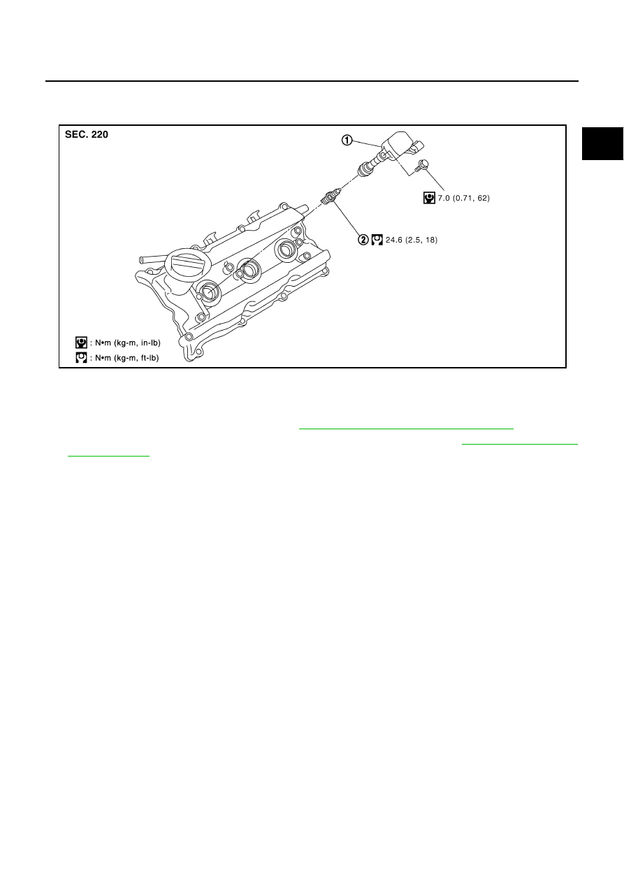
Components
NBS000K2
Removal and Installation
NBS000K3
REMOVAL
1.
Remove engine cover with power tool. Refer to
EM-18, "INTAKE MANIFOLD COLLECTOR"
.
2.
Remove air cleaner case and air duct (for ignition coil of left bank side). Refer to
3.
Move aside harness, harness bracket, and hoses located above ignition coil.
4.
Disconnect harness connector from ignition coil.
5.
Remove ignition coil.
CAUTION:
Do not shock it.
INSTALLATION
Install in the reverse order of removal.
1.
Ignition coil
2.
Spark plug
PBIC4751E