Geely Emgrand X7. Manual part - 672


  Главная      Geely     Geely Emgrand X7 - Manual


поиск по сайту          


содержание   ..   670  671  672  673  ..


Geely Emgrand X7. Manual part - 672


13. Install and tighten horizontal pin bolt for 

connection of steering wheel and steering pipe 
column knuckle. 

Torque: 30Nm (Metric) 22 . 2lb-ft(English system) 

14.   Lower the vehicle. 

15.   Install left and right front wheels. 

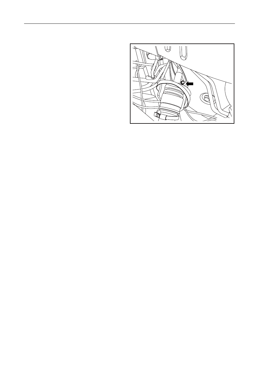
16.   Add booster steering fluid. 


NL12-0073b

2687


12.6.4.5 Rear subframe replacement 

Dismantlement Procedure 

1.    For lifting of the vehicle, see 

1.3 Lifting of Vehicle

2.    For dismantling of rear muffler, refer to 

2.7.6.4 Replacement of rear muffler

3.    Use pallet jack to support rear auxiliary frame. 

4.    For dismantling of rear vertical arms on both sides, refer to 

4.3.7.8 Replacement of rear vertical arm

5.    For removal of the rear suspension #1 swing arms on both sides, see

 4.3.7.3 Replacement of Rear Suspension 

Swing Arms. 

6.    For removal of the rear suspension #2 swing arms on both sides, see 

4.3.7.2 Replacement of Rear Suspension 

Swing Arms. 

7.    For dismantlement of top swing arms for both side rear suspensions, see 

4.3.7.7 Replacement of Rear 

Suspension Top Swing Arms. 

8.    For dismantlement of the parking brake control mechanism assembly control cable, see 

6.5.5.3 Replacement 

of Parking Brake Control Mechanism Assembly Control Cable. 

NL12-0084b

9.  For dismantlement of two rear wheel speed 

sensors, see 

6.6.7.3 Replacement of Wheel Speed 

Sensors (Rear).


10.   For dismantling of rear stabilizer rod connecting 

rod on both sides, refer to 

4.3.7.5 Replacement of 

rear stabilizer rod connecting rod

11.   Dismantle rear stabilizer rod. Refer to 

4.3.7.6 rear 

stabilizer rod replacement. 

12. Dismantle rear damper of both sides refer to 

4.3.7.1 rear shock absorber replacement. 

13. For dismantling of support of rear axle ball heads 

on both sides, refer to 

4.3.7.9 Replacement of 

support of rear axle ball head

14. For dismantling of rear wheel hub unit on both 

sides, refer to 

4.3.7.10 Replacement of rear wheel 

hub unit


15. Dismantle fixing bolts on both sides of front 

section of rear auxiliary frame. 


NL12-0085b


2688


16.   Dismantle fixing bolt on both sides of rear end of 

rear auxiliary frame. 

17.  Slowly lower jack and remove rear auxiliary 

frame. 


NL12-0086b

Installation Procedure: 

1.   Use flat plate jack to slowly lift rear auxiliary 

frame. 

2.   Install and tighten fixing bolts on both sides of 

rear end of rear auxiliary frame. 

Torque :200 Nm(Metric)148lb-ft (English system) 


NL12-0086b


2689


3.   Install and tighten fixing bolt on both sides of 

front end of rear auxiliary frame. 

Torque: 150 Nm (Metric) 111 lb-ft (English system) 

4.    Install rear wheel hub units on both sides. 

5.    Install the spindle head bearing seats for the rear 

axles on both sides. 

6.    Install the two side reaer shock absorbers. 

7.    Install the rear stabilizer bar. 

8.    Install the connecting rod between both side rear 

stabilizer bars. 

9.    Install two rear wheel speed sensor . 

10.  Install parking operation mechanical assembly 

cable. 

11.  Install upper swing arm at both side of rear 

suspension. 

12. Install swing arm 2 on both sides of rear 

suspension. 

13. Install swing arm 1 on both sides of rear 

suspension. 

14.   Install rear vertical arm on both sides. 

15.   Install rear muffler. 

16.   Lower the vehicle. 

17.   Install left right rear wheel. 

NL12-0085b

2690


содержание   ..   670  671  672  673  ..