Geely Emgrand X7. Manual part - 353


  Главная      Geely     Geely Emgrand X7 - Manual


поиск по сайту            


содержание   ..   350  351  352  353  354  ..


Geely Emgrand X7. Manual part - 353


The upper support of the 
shock absorber and piston rod 
nut 

M12×1.25 

60-80 44-59  

Mounting support mounting 
bolt of front stabilizer rod 

M12×1.25×30 

79-95 58-70  

Connecting bolt between 
front suspension 
reinforcement plate and body

M12×1.5×30 85-101 

63-75 


Front axle hub nut (drive 
shaft) 

M22×1.5 216 

160 

The locking 
nut hits 
concavely to 
fix. 

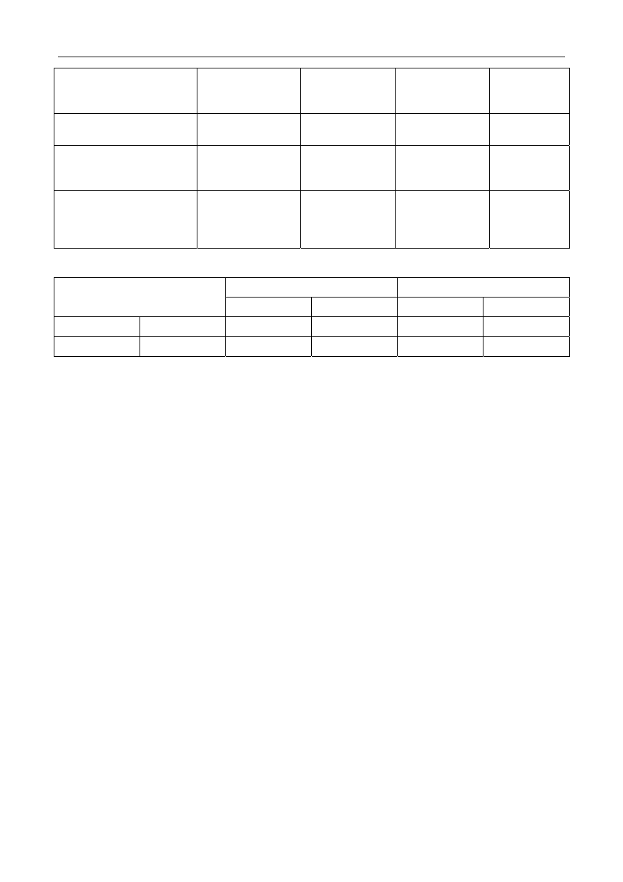
4.2.1.2 General specifications 

No load 

No load 

Wheel runout   

Front Rear  Front Rear 

Upstroke mm/in  93.4/3.6 116.8/4.6 

80.8/3.1 94.5/16.1 

Upstroke mm/in 

67.5/2.7  73.7/3 

80/3.1 

96/3.7 


1411


4.2.2 Description and operation 

4.2.2.1 Description and operation 

The front suspension system of the vehicle plays the role in furthest increasing the tire and the road surface to 
provide good steering operation and stability as well as ensure the passenger comfort. It can absorb the energy of 
the vertical acceleration speed, so that the wheels are bumped up and down along with the road surface but the 
frame and body are not interfered. The front suspension for this vehicle is an independent strut suspension, which 
consists of the following components: spring, shock absorber and stabilizer bar. 

4.2.3 System operation principle 

4.2.3.1 Suspension system term 

1. Spring 

weight: 

• 

Spring loading weight refers to vehicle weight borned by spring. 

• 

Spring loading weight should be more than unsprung loading weight to obtain normal opeartion 
performance. 

Examples of sprung weight: 

a. 

Body and frame 

b. Load 

or 

cargos 

c. Fuel 

tank 

Sprung part includes: 

a. 

Frame (including the subframe) 

b. 

Body (including the unit body) 

c. 

Power system (engine, transmission and transmission drive axle) 

d. Steering 

gear 

2. Unsprung 

weight: 

• 

Unsprung loading weight refers to vehicle weight which is not borne by spring. 

• 

The smaller the unsprung loading weight is, the better it is, to ensure normal opeartion and traveling 
smoothness. 

Examples of nonsprung weight: 

a. Wheel 

and 

tire 

b. 

Wheel bearing and hub 

c. 

Axle and knuckle 

d. 

Braking components (installed on the wheel) 

Unsprung part includes: 

a. 

Wheel/tire, ball joint, bearing, control arm, I-beam, cross member axle and one-piece drive axle. 

b. 

Stabilizer bar and control rod components. 

c. 

Core shaft, knuckle, brake, etc. 

d. 

The suspension response will be good if the unsprung loaded weight is small. 

3. 

Parts between spring-load weight and unsprung load weight: 

1412


The steering rod, the drive shaft, the stabilizer and the other parts are located between the sprung part and the 
unsprung part. 

4.2.3.2 Operation principle of suspension system component 

1. Spring: 

The rigidity of the spring will affect on the response of the sprung mass when the vehicle is running; the vehicle 
with rigidity too low of the spring can thoroughly eliminate bump and provide extremely stable running feeling; 
however, at the same time, it is easy to dive and crouch in the course of brake and acceleration; and it is easy to 
skew and turn over during turning a corner. The vehicle with rigidity too large of the spring has worse stability on 
the bump road surface; however, the body moves little, which means that the vehicle can also be driven in a 
quicker mode even though turning a corner. Therefore, although the spring itself seems simply, the spring can not 
individually provide an extremely smooth driving feel when designing and realizing these devices on the vehicle 
with a balance between the passenger comfort and handling characteristics of the vehicle. The  performance  of  the 
spring on the aspect of absorbing energy is excellent; however, its capability of dissipating is worse. Therefore, 
the suspension system needs to use a part called as the shock absorber. If not using a damping structure, the spring 
will be bounced off at the uncontrollable speed, release the bump energy absorbed, continually upspring based on 
its frequency until exhaust all energy applied thereon initially. The suspension established on the spring drives the 
vehicle in the jumping mode according to terrain and is not controlled. 

2. Shock 

absorber: 

7

1

5

6

3

4

2

NL04-1001b


1. 

Piston pushing rod 

2. Inner 

cylinder 

3. Outer 

cylinder 

4. Hydraulic 

cylinder. 

5. Piston 

and 

valves 

6. Liquid-storing 

space 

7. 

Internal cylinder bottom valve 

1413


It controls the unexpected spring motion through a process of damping called.The shock absorber slows down and 
reduces the motion of vibratility through converting the kinetic energy of suspension motion into heat energy 
dissipated by hydraulic oil. The upper support of the shock absorber is connected with the frame (i.e., sprung 
weight); and the lower support thereof is connected with the shaft close to the wheel (i.e., unsprung weight). In 
double-cylinder design, one of the most common types of shock absorber is that the upper support is connected 
with the piston rod, the piston rod is connected with the piston, and the piston is located in a cylinder filled with 
hydraulic oil. The inner cylinder is called as a pressure cylinder and the outer cylinder is called as the oil storage 
cylinder. The oil storage drum stores excessive hydraulic oil. When the wheels are on the bump road surface to 
compress and stretch the spring, the power of the spring is transmitted to a shock absorber through an upper 
support and to a piston through a piston rod downward. Holes are opened on the piston. When the piston moves 
up and down in the pressure cylinder, hydraulic oil leaks from those small holes. Because these holes are very 
small, there is still only a small amount of hydraulic oil passing through under the great pressure. 

Therefore,  the 

piston slows down to decelerate the spring. The shock absorber work includes two circles-compression circle and 
stretching circle.The compression cycle refers to that the piston compresses the hydraulic oil therebelow when 
moving downwards; the drawing cycle refers to the hydraulic oil thereabove when the piston moves upward to the 
topside of the pressure cylinder. For a typical vehicle, the resistance to stretching circulation is larger than that to 
compression circulation. You need to also note that the compression circulation controls the motion of the 
unsprung    loaded mass and the tension circulation controls the motion of the relatively heavier spring loaded 
mass. All modern shock absorbers have the speed sensing function--the faster the speed of movement of the 
suspension is, the greater the resistance provided by the shock absorber is. Thus, the shock absorber can be 
regulated according to the road condition; moreover, all unexpected motions possibly incurred in the driving 
vehicle are controlled, including bounce, rollover, brake subduction and acceleration crouch, etc. 

3. Stabilizer 

rod: 

It is matched with the shock absorber to provide additional stability for the moving vehicle. 

The  stabilizer  bar 

is a metal rod crossing the whole axle to effectively connect the two sides of the suspension together. When the 
suspension on one wheel moves up and down, the stabilizer bar can transit the motion to the other wheels. 
Therefore, run more stably to reduce the inclination of the vehicle, particularly, it can counteract the rollover of 
the vehicle on the suspension when turning a corner. 

1414


содержание   ..   350  351  352  353  354  ..