Geely Emgrand X7. Manual part - 351


  Главная      Geely     Geely Emgrand X7 - Manual


поиск по сайту            


содержание   ..  349  350  351  352  ..


Geely Emgrand X7. Manual part - 351


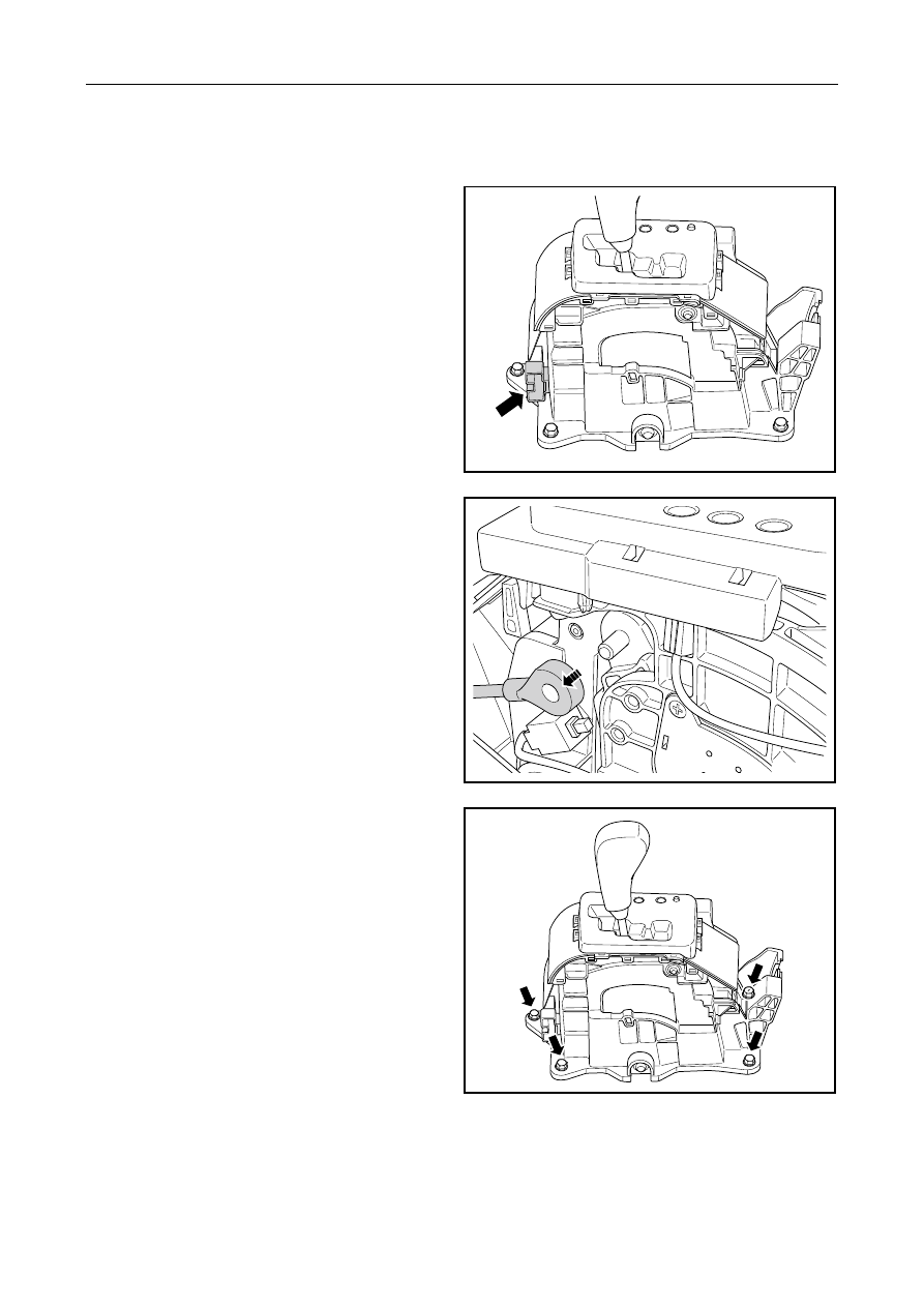
3.5.7.7 Shifter replacement 

Dismantle procedure 

1.  Disconnect the battery negative cable. Refer to 

2.11.8.1 Battery cable disconnection/connection 
procedures. 

2.  Dismantle auxiliary instrument panel on the top 

of selector, refer to 12.8.3.4 Auxiliary Instrument 
Panel Assembly Replacement. 

3.  Disconnect connection of shifter and instrument 

harness harness 


SL03-0001c

4.  Dismantle gearshifting flexible shaft. 


SL03-0002c

5.  Dismantle the shift gear fixing bolts. 

6.  Dismantle the shift gear assembly. 


SL03-0004c


1403


7.  Extract the U-shaped clamping plate from the 

fixing bracket for the shift shaft on the 
transmission side and loosen the nut for fixing the 
transmission shift swing arm with the shift shaft. 


CE03-5003b

8.  Dismantle the bolt for fixing the flexible shaft 

sealing pressure plate and Dismantle the flexible 
shift shaft from the body floor. 


SL03-0003c

Installation procedure:: 

1.  Install gearshifting flexible shaft. 

2.  Install U-clip plate on fixing bracket of 

gearshifting flexible shaft on transmission side 
and nut of fixing transmission gearshifting swing 
arm and gearshafting flexible shaft. 


CE03-5003b


1404


3.  Install shifter assembly and tighten fixing bolt . 

Torque: 16~26 N.m (Metric system) 

9.9~16.2

lb-ft(English system) 


SL03-0004c

4.  Connect gear selector and gearshift flexible shaft.

5.  Install and secure the bolts on the soft shaft 

sealing pressure plate. 

6.  Connect the shift gear with the instrument 

harness connector. 

7.  Install t he floor console over the shift gear. 

8.  Connect battery negative cable. 


SL03-0001c

1405


3.5.7.8 replace automatic transmission control module 

Dismantle procedure 

1.  Disconnect the battery negative cable. Refer to 

2.11.8.1 Battery cable disconnection/connection 
procedures. 

2.  For dismantling of sundries box of instrument, 

refer 12.8.3.2 Replacement of sundries box 

3.  Disconnect connection of Automatic transmission 

control module harness. 

4.  Dismantle fixing bolt of automatic transmission 

control module. 

5.  Dismantle the automatic transmission control 

module. 

NL03-2004c

Installation procedure: 

1.  Install automatic transmission control module 

and tighten fixing bolt. 

2.  Connect wire harness of automatic transmission 

control module. 

3.  Install the glove box of instrument panel. 

4.  Connect battery negative cable. 


NL03-2003c


1406


содержание   ..  349  350  351  352  ..