Geely Emgrand X7. Manual part - 263


  Главная      Geely     Geely Emgrand X7 - Manual


поиск по сайту            


содержание   ..   260  261  262  263  264  ..


Geely Emgrand X7. Manual part - 263


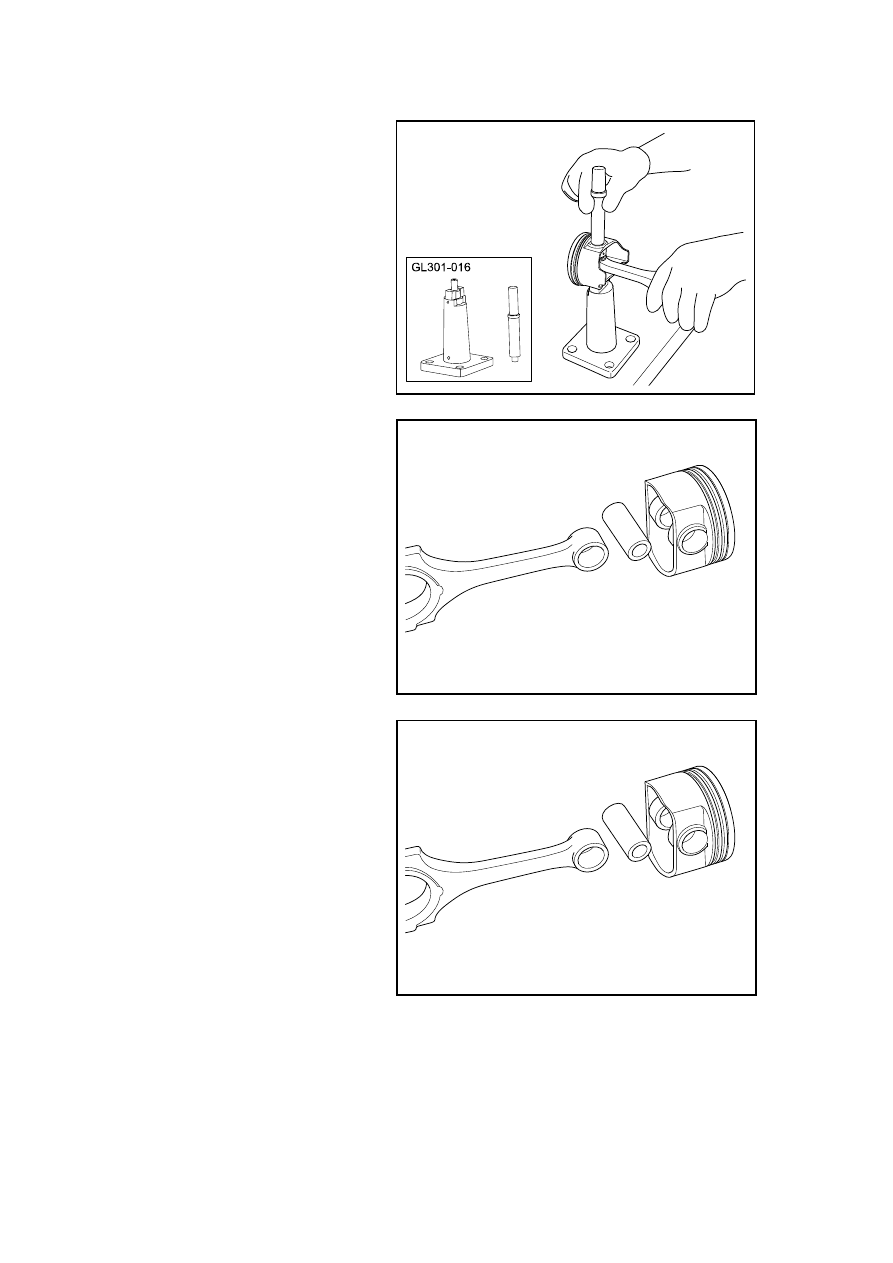
8.  With a special tool GL301-016, 

remove the piston pin. 

FE02-0278b

9. Disassemble connecting rod, 

piston pin and piston are shown 
in the graph. 

FE02-0279b

Installation Procedure: 

1.  Install piston pin, connecting rod 

and piston. 

Note: During installation, make the 
dot on the connecting rod bearing 
cover facing towards the same 
direction as the dot mark on the 
piston.
 

FE02-0279b

1051

2.  Install the piston pin circlip. 

FE02-0281b

3. Confirm  normal  movements 

between the piston and rod 
without any interference. 

4.  Inspect piston pin and connecting 

rod clearance. 

Standard Value 

0.005~0.011mm(Metric) 

0.0002~0.0004in (English system) 

5.  Inspect the piston and piston pin 

clearance. 

Standard Value 

0.005-(-0.001)mm(Metric) 

FE02-0282b

0.0002-(-0.00003)in(English system) 

6.  Install the oil ring. 

7.  Install the oil ring’s lower ring 

combination. 

FE02-0283b

1052

8.  Install the oil ring’s upper ring 

combination. 

FE02-0284b

9.  Install the second air ring. 

Note: the face with letter faces 
toward the top end of the piston!
 

FE02-0285b

10.  Install first air ring. 

Note: the face of the piston ring with 
inner chamber faces toward the top 
end of the piston! 

11. Apply the engine oil to the 

connecting rod bearings and 
install the connecting rod journal 
and the bearing cap. 

12.  Install connect rod to crankshaft , 

check if connecting bearing 
clearance meet capacity 
tolerance. Refer 

to"2.13.1.2 

engine mechanical system 
specification" 

FE02-0286b

Standard Value 

(0.020)~(0.044)mmMetric 

(0.0007)~(0.0017) in (English system) 

13.  Install and inspect the qualified piston connecting rod components.

1053

2.13.8.20 Valve Clearance Adjustment 

1.  Dismantle the plastic shield of engine. Refer to 2.13.8.1 Replacement of Plastic Shield of 

Engine. 

2.  Refer to 2.10.8.3 "Replacement of Ignition Coil" to dismantle the ignition coil. 

3.  Refer to 2.13.8.2 "Replacement 

of Cylinder Hood Cover" to 
dismantle the cylinder hood 
cover. 

4.  Dismantle timing chain cover, 

rotate crankshaft to make the 1st 
cylinder locate on upper 
compression stop position. Refer 
to "2.13.8.9 time chain cover". 
Replacement 

5.  Inspect valve clearance. Use the 

plug gage to measure valve 
clearance value, as arrows shown 
in the graphic and record the 
valve location and tolerance that 
exceeds the tolerance. 

FE02-0287b

6.  Rotate the crankshaft one circle 

(360 °), making the cylinder No. 
4 stop at the compression TDC 
position. 

Measure the valve 

clearance as arrow pointed in the 
graph and record the clearance. 

FE02-0288b

7.  Use a jack to support the engine. 

Dismantle the timing chain. 
Refer to 2.13.8.10 "Replacement 
of Timing Chain" 

8.  Refer to 2.13.8.12 “Replacement 

of Camshaft” to dismantle the 
camshaft. 

9.  Remove the valve lifter that 

exceeds the tolerances. Use 
outside diameter micrometer to 
measure the thickness, according 
to the following formula 
calculate the thickness of the new 
valve lifters. 

FE02-0289b

1054


содержание   ..   260  261  262  263  264  ..