Geely Emgrand X7. Manual part - 94


  Главная      Geely     Geely Emgrand X7 - Manual


поиск по сайту            


содержание   ..   90  91  92  93  94  95  ..


Geely Emgrand X7. Manual part - 94


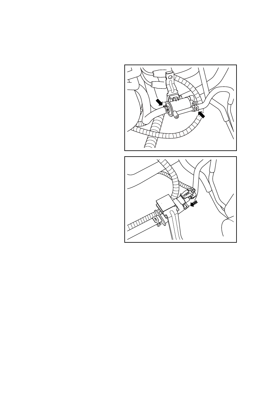
2.4.6.3 Replacement of Canister Solenoid Valve 

Dismantlement Procedure 

Warning: Refer to Warning on Battery Disconnection in Warnings and Precautions. 

1.  Disconnect the battery negative 

electrode cable. Refer to 2.12.6.1 
Battery Disconnection. 

2.  Remove the canister solenoid 

valve from the retaining bracket. 

3. Disconnect canister solenoid 

valve harness connector. 

4.  Disconnect the canister solenoid 

valve vacuum tube. 

5. Dismantle Canister Solenoid 

Valve 

NL02-0076b

Installation Procedure: 

1.  Install Canister Solenoid Valve 

2.  Connect canister solenoid valve 

harness connector. 

3.  Connect canister solenoid valve 

vacuum tube. 

4.  Install the canister solenoid valve 

to the retaining bracket. 

5.  Connect battery negative cable. 

NL02-0075b

375

2.4.6.4 Replacement of Canister 

Dismantlement Procedure 

1.  Lifting and Jacking the Vehicle 

Warning: Refer to "Warning on 
Vehicle Lifting and Jacking" in 
"Warnings and Precautions". 

2.  Loosen canister hose clamp and 

separate the hose. 

3.  Dismantle canister fixing bolt 2. 

2

2

2

1

1

1

NL02-0077b

Installation Procedure: 

1.  Connect canister hose and install 

hose clamp. 

2.  Dismantle canister fixing bolt 2. 

Torque: 8 Nm (Metric) 6 lb-ft (English 
system) 

3. Lower 

the 

vehicle. 

2

2

2

1

1

1

NL02-0077b

376

2.5 Engine Anti-theft System 

2.5.1 Specifications 

2.5.1.1 Fastener Specifications 

Specification 

Fastener Name 

Model 

Metric (N.m) 

English system 
(lb-ft) 

Fixing Bolts of Electric 
Anti-theft Control Module 

M6×16 7-9 

5.2-6.6 

2.5.2 Description and Operation 

2.5.2.1 Description and Operation 

The engine anti-theft locking system can prevent the theft of the vehicle via preventing the 
operation on the engine. The engine anti-theft locking system can prevent the startup of the vehicle. 
If engine anti-theft locking system cannot identify the transponder code of the ignition key, the 
operational functions of the engine will be prohibited.  Engine anti-theft locking system and 
remote anti-theft system are operated independently. Engine anti-theft locking system and remote 
anti-theft system have no interaction. 

Engine anti-theft system components are listed below: 

– 

Engine anti-theft system control module (IMMO) 

– 

Engine Control Module (ECM) 

– 

Electronic Anti-theft Coil (Engine Anti-theft System, Antennas) 

– 

Ignition Key (Transponder) 

1. Ignition 

Key 

(Transponder) 

It contains the microprocessor and transceiver coil. Through the magnetic field generated by EAS 
Coil, it gets the energy and information from the magnetic field, and decrypts and encrypts the 
information before transmitting the information back to the EAS Coil. 

2.  Electronic Anti-theft Coil (Engine Anti-theft System, Antennas) 

EAS Coil is surround-mounted to the ignition lock core. When the ignition key is inserted into the 
ignition lock core and turns the ignition switch to the “ON” position, the induced magnetic field is 
generated to transfer the communication signal between the anti-theft controller and the 
transponder. Integrated on the electronic anti-theft coil is a light- emitting diode controlled by the 
interior lighting circuit in order to facilitate the driver to locate the ignition cylinder. 

3.  Engine Anti-theft System Control Module 

The engine anti-theft system control module is arranged below the middle part of the dashboard; 
after receiving the transponder information transmitted from the electronic anti-theft coil, the 
engine anti-theft system control module compares the information with the key information read 
in the memory, so as to decide whether sending fuel commissioning/forbidding command. 

Note: If the anti-theft system can not get the ignition key transponder information, it will not 
send any signal to the engine control module. 

4.  Engine Control Module 

Engine control module is installed under the passenger side of instrument panel, near the 
air-conditioning blower. Based on the signal received from the engine control module anti-theft 
system, it sends instruction to enable / disable fuel injection. 

Based on the instruction received from the engine control module anti-theft system, engine control 

377

module will decide whether to send the engine control module to the body lock / unlock status 
information. 

Based on the instruction received from the engine control module anti-theft system, engine control 
module will decide whether to send to the combination instrument the request of  "Light the 
engine anti-theft system warning lamp". 

378


содержание   ..   90  91  92  93  94  95