Geely Emgrand X7. Manual part - 91


  Главная      Geely     Geely Emgrand X7 - Manual


поиск по сайту            


содержание   ..   90  91  92  ..


Geely Emgrand X7. Manual part - 91


2.4.2.3 Positive Crankcase Ventilation(PCV) System 

Compressed combustion gases fleeing into the crankcase through the piston rings is known as 
channeling gas. through the piston rings is known as channeling gas. Channeling gas contains 
nitrogen oxides, carbon monoxide and hydrocarbons. Crankcase ventilation system prevents the 
channeling gas entering into the atmosphere. Crankcase ventilation system will force the 
channeling gas crankshaft back into the intake system and the combustion chamber. Positive 
crankcase ventilation system consists of the following components: 

z  Positive Crankcase Ventilation Valve 

z  Crankcase Ventilation Tube 

z  Hose and Connectors 

1. Operation 

The main control device is the positive crankcase ventilation (PCV) valve. Positive crankcase 
ventilation valve calculates the channeling air flow according to manifold vacuum signal. Lower 
positive crankcase ventilation valve parts below the O-ring are exposed to a vacuum in the intake 
manifold, parts located between the lower and upper O-ring are exposed to the crankcase gases. 
Positive crankcase ventilation valve allows some internal vacuum pressure through the valve 
orifice, and form the low- pressure condition inside the crankcase. The channeling crankcase gas is 
then sucked into intake system and burnt in the normal combustion process. The channeling gas 
entering into the intake manifold must be accurately controlled in order to maintain idle quality. It 
is necessary to use the correct and proper calibration of the positive crankcase ventilation valve. 
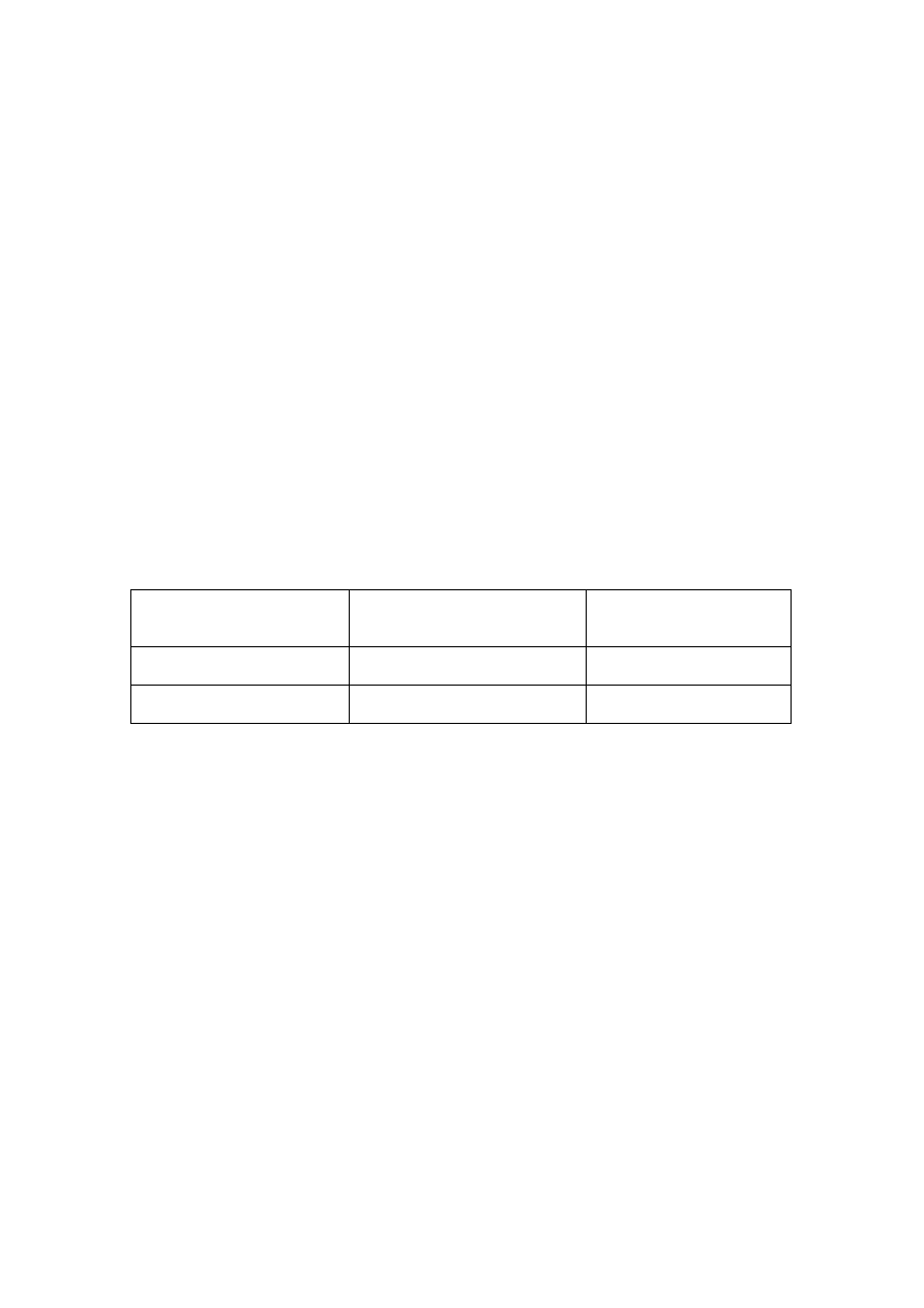
Relationship between the Channeling air flow and engine manifold vacuum is shown in the table 
below: 

Manifold Vacuum 

Positive crankcase ventilation 
valve Opening 

Channeling Air Flow 

Low Large  High 

High Small  Low 

2.  The Consequences Of Abnormal Operation 

Valve or hose blockage may lead to the following conditions: 

Poor engine idling. 

Engine stalls or engine idle speed is too low. 

Engine crankcase pressure is too high. 

Engine oil leak. 

Engine oil enters into the air filter. 

Engine has sludge. 

Engine oil consumption. 

Excessive exhaust emissions. 

363

2.4.3 System operating principle 

2.4.3.1 Heated Type Oxygen Sensor Operating Principle 

¾  Oxygen sensor has a sensing element, which is a porous ceramic tube, the outer wall 

surrounded by the engine exhaust and inside connecting to the atmosphere. Sensing ceramic 
pipe wall is a solid electrolyte that contains electric heating pipes. When the sensor ceramic 
tube temperature reaches 350°C (662 °F), it will have a solid electrolyte properties. 

¾  The function of oxygen sensor is realized through changing the concentration difference of 

oxygen ions inside and outside the sensing ceramic tube into the voltage signal output. 

¾  The output voltage level is due to movement caused internal electronic ceramic tubes. 

¾  Meet EOBD vehicles self inspect whether the sensor information is accurate. 

¾  Heated resistor resistance at room temperature is 2.4-4.9 Ω. 

Heated type oxygen sensor repair precautions: 

1.  During the oxygen sensor repair procedure, it is prohibited to use cleaning agent, oily liquids 

or volatile solids. 

2.  After the Replacement of oxygen sensor, apply a layer of anti-rust oil to oxygen sensor 

threads to prevent rust. All the oxygen sensors consist of cables. The electrical connector is at 
the other end of the cable. The external packaging is anti-fire sleeve. A new oxygen sensor 
will be coated with anti-rust oil on the thread, during installation do not remove these 
anti-rust oil. 

2.4.3.2 Canister Solenoid Valve Operating Principle 

¾  Canister solenoid valve consists of the electromagnetic coil, armature and valves so on. 

canister inlet port has a filter. 

¾  On one hand, air flow through the canister solenoid valve is related to ECM output to the 

canister solenoid valve electrical pulse duty cycle; on the other hand, it is related to the 
pressure difference between the Canister solenoid valve inlet port and outlet port. When there 
is no electrical pulses, the canister solenoid valve will be turned off. 

¾  According to the engine sensors provided signals, ECM controls the canister solenoid valve 

power-on time, indirectly controls the air flow amount. 

¾  When the engine coolant temperature, engine running time and engine load etc. meet the 

preset requirements, ECM will instruct canister solenoid valve to start working. In the 
following situations canister solenoid valve will not work:                 

(1) Engine cold start after a time.   

(2) Engine coolant temperature is relatively low.   

(3) Engine idling.   

(4) Engine load is high.   

(5) Important sensor in system has fault.     

364

2.4.4 Component position


2.4.4.1 Canister Position Diagram 

NL02-2186b

1

2


1. Canister 

Assembly 

2. Canister 

Ventilation 

Filter 

365

2.4.4.2 Canister Solenoid Valve Position Diagram 

NL02-1004e


366


содержание   ..   90  91  92