Dodge Dakota (ND). Manual - part 966


  Index      Dodge     Dodge Dakota (ND) 2005 - service repair manual 2005 year


Search            


Content   ..  964  965  966  967   ..


Dodge Dakota (ND). Manual - part 966


FLUID LEAKAGE

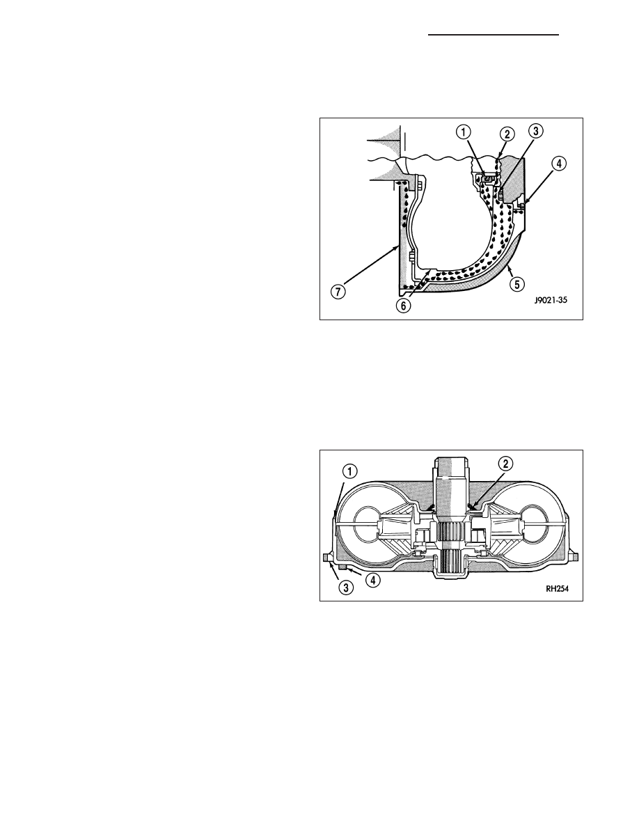
FLUID LEAKAGE - TORQUE CONVERTER HOUSING AREA

When diagnosing converter housing (5) fluid leaks,
three actions must be taken before repair:

1. Verify proper transmission fluid level.

2. Verify that the leak originates from the converter

housing area and is transmission fluid.

3. Determine the true source of the leak.

Fluid leakage at or around the torque converter area
may originate from an engine oil leak (7). The area
should be examined closely. Factory fill fluid is red
and, therefore, can be distinguished from engine oil.

Some suspected converter housing fluid leaks may
not be leaks at all. They may only be the result of
residual fluid in the converter housing, or excess fluid
spilled during factory fill, or fill after repair. Converter
housing leaks have several potential sources. Through
careful observation, a leak source can be identified
before removing the transmission for repair.

Pump seal (1) leaks tend to move along the drive hub and onto the rear of the converter. Pump o-ring or pump
body leaks follow the same path as a seal leak. Pump attaching bolt (3) leaks are generally deposited on the inside
of the converter housing (5) and not on the converter itself. Pump seal (1) or gasket (4) leaks usually travel down
the inside of the converter housing.

TORQUE CONVERTER LEAKAGE

Possible sources of torque converter leakage are:

Torque converter weld leaks at the outside diam-
eter weld (1).

Torque converter hub weld (2).

STANDARD PROCEDURE - ALUMINUM THREAD REPAIR

Damaged or worn threads in the aluminum transmission case and valve body can be repaired by the use of Heli-
Coils

T

, or equivalent. This repair consists of drilling out the worn-out damaged threads. Then tap the hole with a

special Heli-Coil

T

tap, or equivalent, and installing a Heli-Coil

T

insert, or equivalent, into the hole. This brings the

hole back to its original thread size.

Heli-Coil

T

, or equivalent, tools, and inserts are readily available from most automotive parts suppliers.

21 - 256

AUTOMATIC TRANSMISSION 42RLE - SERVICE INFORMATION

ND

REMOVAL

1. Disconnect the negative battery cable.

2. Raise and support the vehicle

3. Remove any necessary skid plates. (Refer to 13 -

FRAMES & BUMPERS/FRAME/TRANSFER CASE
SKID PLATE - REMOVAL)

4. Mark propeller shaft and axle companion flanges

for assembly alignment.

5. Remove the rear propeller shaft. (Refer to 3 - DIF-

FERENTIAL & DRIVELINE/PROPELLER SHAFT/
PROPELLER SHAFT - REMOVAL)

6. Remove the front propeller shaft, if necessary.

(Refer to 3 - DIFFERENTIAL & DRIVELINE/PRO-
PELLER

SHAFT/PROPELLER

SHAFT

-

REMOVAL)

7. Disconnect wires from the input (1) and output (2)

speed sensors.

8. Disconnect wires from the transmission range sen-

sor (3).

9. Disconnect wires from the solenoid/pressure switch

assembly.

ND

AUTOMATIC TRANSMISSION 42RLE - SERVICE INFORMATION

21 - 257

10. Remove the bolts holding the exhaust crossover

pipe to the pre-catalytic converter pipe flanges (1).

11. Remove the bolts holding the exhaust crossover

pipe to the catalytic converter flange.

12. Disconnect gearshift cable (1) from transmission

manual valve lever (3).

13. Disengage the shift cable (1) from the cable sup-

port bracket (2).

21 - 258

AUTOMATIC TRANSMISSION 42RLE - SERVICE INFORMATION

ND

14. Remove the starter motor.

15. Remove the engine to transmission collar.

16. Rotate crankshaft in clockwise direction until con-

verter bolts are accessible. Then remove bolts
one at a time. Rotate crankshaft with socket
wrench on dampener bolt.

17. Disconnect the transmission vent hose from the

transmission.

18. Remove transfer case. (Refer to 21 - TRANSMIS-

SION/TRANSFER CASE - REMOVAL)

19. Support rear of engine with safety stand or jack.

20. Raise transmission slightly with service jack to

relieve load on crossmember and supports.

21. Remove bolts securing rear support and cushion

to transmission and crossmember.

22. Remove bolts attaching crossmember to frame

and remove crossmember.

23. Disconnect transmission fluid cooler lines (1) at

transmission fittings (3) and clips (2).

24. Remove all remaining converter housing bolts.

25. Carefully work transmission and torque converter

assembly rearward off engine block dowels.

26. Hold torque converter in place during transmission

removal.

27. Lower transmission and remove assembly from

under the vehicle.

28. To remove torque converter, carefully slide torque

converter out of the transmission.

DISASSEMBLY

NOTE: If the transmission is being reconditioned (clutch/seal replacement) or replaced, it is necessary to
perform the Quick Learn Procedure using the scan tool (Refer to 8 - ELECTRICAL/ELECTRONIC CONTROL
MODULES/TRANSMISSION CONTROL MODULE - STANDARD PROCEDURE).

NOTE: Tag all clutch pack assemblies, as they are removed, for reassembly identification.

CAUTION: Do not intermix clutch discs or plates as the unit might then fail.

Before disassembling transmission, move the shift lever clockwise as far as it will go and then remove the shift
lever.

ND

AUTOMATIC TRANSMISSION 42RLE - SERVICE INFORMATION

21 - 259


Content   ..  964  965  966  967   ..