Dodge Dakota (ND). Manual - part 965


  Index      Dodge     Dodge Dakota (ND) 2005 - service repair manual 2005 year


Search            


Content   ..  963  964  965  966   ..


Dodge Dakota (ND). Manual - part 965


The process of elimination can be used to detect any unit which slips and to confirm proper operation of good units.
Road test analysis can diagnose slipping units, but the cause of the malfunction cannot be determined. Practically
any condition can be caused by leaking hydraulic circuits or sticking valves.

HYDRAULIC PRESSURE TESTS

Pressure testing is a very important step in the diag-
nostic procedure. These tests usually reveal the cause
of most transmission problems.

Before performing pressure tests, be certain that fluid
level and condition, and shift cable adjustments have
been checked and approved. Fluid must be at operat-
ing temperature (150 to 200 degrees F.).

Install an engine tachometer, raise vehicle on hoist
which allows the wheels to turn, and position tachom-
eter so it can be read.

Using

special

adapters

L-4559,

attach

300

psi

gauge(s) C-3293SP to the port(s) required for test
being conducted.

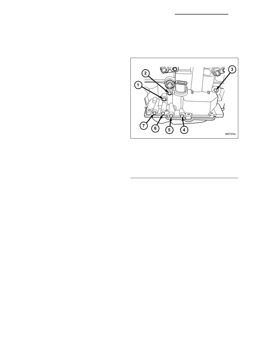
Test port locations are shown in the Pressure Taps
graphic.

TEST ONE - SELECTOR IN MANUAL 1 (1st Gear)

NOTE: This test checks pump output, pressure regulation and condition of the low/reverse clutch hydraulic
circuit and shift schedule.

1. Attach pressure gauge to the low/reverse clutch tap.

2. Move selector lever to the MANUAL 1 position.

3. Allow vehicle wheels to turn and increase throttle opening to achieve an indicated vehicle speed to 20 mph.

4. Low/reverse clutch pressure should read 115 to 145 psi.

TEST TWO - SELECTOR IN MANUAL 2 (Second Gear)

NOTE: This test checks the underdrive clutch hydraulic circuit as well as the shift schedule.

1. Attach gauge to the underdrive clutch tap.

2. Move selector lever to the MANUAL 2 position.

3. Allow vehicle wheels to turn and increase throttle opening to achieve an indicated vehicle speed of 30 mph.

4. In second gear the underdrive clutch pressure should read 110 to 145 psi.

TEST TWO A - SELECTOR IN DRIVE (OD ON - Fourth Gear)

NOTE: This test checks the underdrive clutch hydraulic circuit as well as the shift schedule.

1. Attach gauge to the underdrive clutch tap.

2. Move selector lever to the DRIVE position. Verfy that the OD switch is ON.

Pressure Taps

1 - TORQUE CONVERTER CLUTCH OFF
2 - REVERSE
3 - LOW/REVERSE
4 - 2/4
5 - UNDERDRIVE
6 - TORQUE CONVERTER CLUTCH ON
7 - OVERDRIVE

21 - 252

AUTOMATIC TRANSMISSION 42RLE - SERVICE INFORMATION

ND

3. Allow wheels to rotate freely and increase throttle opening to achieve an indicated speed of 40 mph.

4. Underdrive clutch pressure should read below 5 psi. If not, than either the solenoid assembly or controller is at

fault.

TEST THREE - SELECTOR IN DRIVE (OD OFF - Third and Second Gear)

NOTE: This test checks the overdrive clutch hydraulic circuit as well as the shift schedule.

1. Attach gauge to the overdrive clutch tap.

2. Move selector lever to the DRIVE position.

3. Allow vehicle wheels to turn and increase throttle opening to achieve an indicated vehicle speed of 20 mph.

4. Overdrive clutch pressure should read 74 to 95 psi.

5. Move selector lever to the DRIVE position and increase indicated vehicle speed to 30 mph.

6. The vehicle should be in second gear and overdrive clutch pressure should be less than 5 psi.

TEST FOUR - SELECTOR IN DRIVE (OD ON - Fourth Gear)

NOTE: This test checks the 2/4 clutch hydraulic circuit.

1. Attach gauge to the 2/4 clutch tap.

2. Move selector lever to the DRIVE position.

3. Allow vehicle front wheels to turn and increase throttle opening to achieve an indicated vehicle speed of 30 mph.

Vehicle should be in fourth gear.

4. The 2/4 clutch pressure should read 75 to 95 psi.

TEST FIVE-SELECTOR IN DRIVE (OD ON - Fourth Gear, CC on)

NOTE: These tests check the torque converter clutch hydraulic circuit.

1. Attach gauge to the torque converter clutch off pressure tap.

2. Move selector lever to the DRIVE position.

3. Allow vehicle wheels to turn and increase throttle opening to achieve an indicated vehicle speed of 50 mph.

Vehicle should be in 4th gear, CC on.

CAUTION: Both wheels must turn at the same speed.

4. Torque converter clutch off pressure should be less than 5 psi.

5. Now attach the gauge to the torque converter clutch on pressure tap.

6. Move selector to the OD position.

7. Allow vehicle wheels to turn and increase throttle opening to achieve an indicated vehicle speed of 50 mph.

8. Verify the torque converter clutch is applied mode using the RPM display of the scan tool.

9. Torque converter clutch on pressure should be 60-90 psi.

TEST SIX-SELECTOR IN REVERSE

NOTE: This test checks the reverse clutch hydraulic circuit.

1. Attach gauge to the reverse and low/reverse clutch tap.

2. Move selector lever to the REVERSE position.

3. Read reverse clutch pressure with output stationary (foot on brake) and throttle opened to achieve 1500 rpm.

4. Reverse and low/reverse clutch pressure should read 165 to 235 psi.

TEST RESULT INDICATIONS

1. If proper line pressure is found in any one test, the pump and pressure regulator are working properly.

2. Low pressure in all positions indicates a defective pump, a clogged filter, or a stuck pressure regulator valve.

ND

AUTOMATIC TRANSMISSION 42RLE - SERVICE INFORMATION

21 - 253

3. Clutch circuit leaks are indicated if pressures do not fall within the specified pressure range.

4. If the overdrive clutch pressure is greater than 5 psi in Step 6 of Test Three, a worn reaction shaft seal ring or

a defective solenoid assembly is indicated.

5. If the underdrive clutch pressure is greater than 5 psi in Step 4 of Test Two-A, a defective solenoid/pressure

switch assembly or controller is the cause.

ALL PRESSURE SPECIFICATIONS ARE PSI (on hoist, with wheels free to turn)

Gear Selector

Position

Actual Gear

PRESSURE TAPS

Under-

drive

Clutch

Over-

drive

Clutch

Reverse

Clutch

Torque

Converter

Clutch

Off

Torque

Converter

Clutch

On

2/4

Clutch

Low/

Reverse

Clutch

PARK - 0 mph *

PARK

0-2

0-5

0-2

60-110

45-100

0-2

115-
145

REVERSE - 0 mph *

REVERSE

0-2

0-7

165-235

50-100

35-85

0-2

165-
235

NEUTRAL - 0 mph *

NEUTRAL

0-2

0-5

0-2

60-110

45-100

0-2

115-
145

Low - 20 mph #

FIRST

110-145

0-5

0-2

60-110

45-100

0-2

115-
145

Third - 30 mph #

SECOND

110-145

0-5

0-2

60-110

45-100

115-
145

0-2

Third - 45 mph #

DIRECT

75-95

75-95

0-2

60-90

45-80

0-2

0-2

OD - 30 mph #

OVERDRIVE

0-2

75-95

0-2

60-90

45-80

75-95

0-2

OD - 50 mph #

OVERDRIVE WITH
TCC

0-2

75-95

0-2

0-5

60-95

75-95

0-2

* Engine Speed at 1500 rpm

# CAUTION: Both wheels must be turning at same speed.

CLUTCH AIR PRESSURE TESTS

Inoperative clutches can be located by substituting air
pressure for fluid pressure. The clutches may be
tested by applying air pressure to their respective pas-
sages after the valve body has been removed. Use
Special Tool 6599-1 (1) and 6599-2 (1) to perform test.

To make air pressure tests, proceed as follows:

NOTE: The compressed air supply must be free of
all dirt and moisture. Use a pressure of 30 psi.

1. Remove oil pan and valve body. (Refer to 21 -

TRANSMISSION/AUTOMATIC

-

42RLE/VALVE

BODY - REMOVAL)

2. Apply air pressure to the holes in the special tool

(1), one at a time.

3. Listen for the clutch to apply. It will give a slight

thud sound. If a large amount of air is heard escap-
ing, the transmission must be removed from vehi-
cle, disassembled and all seals inspected.

Air Pressure Test Plate

1 - AIR PRESSURE TEST PLATES
2 - 2/4 CLUTCH RETAINER HOLE

21 - 254

AUTOMATIC TRANSMISSION 42RLE - SERVICE INFORMATION

ND

2/4 CLUTCH

Apply air pressure to the feed hole located on the 2/4 clutch retainer (2). Look in the area where the 2/4 piston
contacts the first separator plate and watch carefully for the 2/4 piston to move rearward. The piston should return
to its original position after the air pressure is removed.

OVERDRIVE CLUTCH

Apply air pressure to the overdrive clutch apply passage and watch for the push/pull piston to move forward. The
piston should return to its starting position when the air pressure is removed.

REVERSE CLUTCH

Apply air pressure to the reverse clutch apply passage and watch for the push/pull piston to move rearward. The
piston should return to its starting position when the air pressure is removed.

LOW/REVERSE CLUTCH

Apply air pressure to the low/reverse clutch feed hole passage. Look in the area where the low/reverse piston con-
tacts the first separator plate. Watch carefully for the piston to move forward. The piston should return to its original
position after the air pressure is removed.

UNDERDRIVE CLUTCH

Because this clutch piston cannot be seen, its opera-
tion is checked by function. Use an air nozzle (2) to
apply air pressure is to the low/reverse or the 2/4
clutch opening in Test Plate 6599-1 (2). This locks the
output shaft. Use a piece of rubber hose wrapped
around the input shaft and a pair of clamp-on pliers to
turn the input shaft. Next apply air pressure to the
underdrive clutch. The input shaft should not rotate
with hand torque. Release the air pressure and con-
firm that the input shaft will rotate.

ND

AUTOMATIC TRANSMISSION 42RLE - SERVICE INFORMATION

21 - 255


Content   ..  963  964  965  966   ..