DAF 95XF. Manual - part 478


  Index      DAF     DAF 95XF Series - service repair manual


Search            


Content   ..  476  477  478  479   ..


DAF 95XF. Manual - part 478


3

GEARBOX, MECHANICAL

Inspection and adjustment

3-4

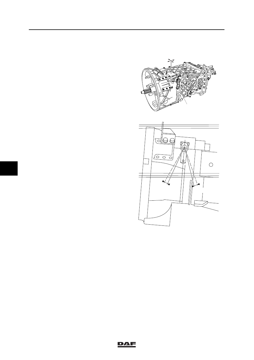
3.4 INSPECTION AND ADJUSTMENT OF GEARBOX COVER

Inspection of gear box cover
1.

Disconnect the shift control from the
lever (1).

2.

Check in 5th and 6th gear how much farther
the lever (1) can be pushed. This travel
distance (P) should be equal for both gears.

Adjustment of gear box cover

Note:
If the travel distance (P) differs, the following
steps must be completed.

1.

Slightly loosen the control housing fixing
bolts.

2.

Move the control housing forward and
backward such, that this travel distance is
equal for both gears (direction A-A).

3.

Repeat step 2 for the 7th and 8th gear.

4.

If the 1st and 2nd gears cannot be
engaged, move the control housing
transversely (direction B-B).

5.

Tighten the control housing fixing bolts.

6.

Check manually that the selector shaft runs
smoothly and returns easily to the rest
position.

7.

Check whether the travel distance is equal
in all gears.

8.

If required, repeat the entire procedure.

Note:
To obtain a better stop, fit a tighter stop spring
(191N instead of 168N) (DAF no. 1341343).

9.

Install the shift control.

V300257

1

A

A

B

B

P

P

6/8th gear

5/7th gear

V300258

6

ǹ 0002

3

Removal and installation

GEARBOX, MECHANICAL

4-1

4. REMOVAL AND INSTALLATION

4.1 REMOVAL AND INSTALLATION OF THE GEARBOX

Removing the gearbox
1.

Disconnect the earth lead from the battery
pole.

2.

Remove the insulation at the rear end of the
engine and underneath the gearbox.

3.

Disconnect the drive shaft from the gearbox
flange and suspend the drive shaft from the
chassis.

4.

Remove the clutch servo without
disconnecting the line. Remove the fixing
bolts from the clutch servo and suspend the
clutch servo assembly from the chassis.

5.

Remove the spare wheel, if necessary.

6.

Disconnect the connectors of the gearbox
wiring harness.

7.

Disconnect the air pipes from the central air
distribution block at the side of the gearbox.

Note:
If the gearbox is equipped with MGS or
servo shift, the following steps must be
completed.

8.

Remove the ball joint from the control rod
on the gearbox arm, as well as the torque
rod which is mounted on the clutch housing,
and suspend the gearbox control from the
chassis.

V300138

6

ǹ 0002

3

GEARBOX, MECHANICAL

Removal and installation

4-2

Note:
If the gearbox is equipped with HGS, the
following steps must be completed.

9.

Remove the fixing nuts (1) from the gear
engaging cylinders mounted on the gearbox
brackets on the gearbox, as well as the
fixing bolts (2) from the gear engaging
cylinders mounted on the gearbox arm, and
suspend the cylinder assemblies so that
they are entirely separated from the
gearbox.

10. If necessary, remove the section of the

exhaust pipe underneath the gearbox.

11. Place a jack underneath the gearbox and

remove the gearbox fixing bolts around the
clutch housing.

Note:
When the gearbox is removed from the
engine, the thrust bearing remains in the
clutch release assembly.

12. Use the jack to pull the gearbox from the

engine and remove the gearbox.

Installing the gearbox
1.

Before positioning the gearbox, one gear
should be engaged in order to allow the
input shaft to slide into the clutch plate
during installation.

2.

Install the thrust bearing over the sliding
bush and check whether the circlip in the
clutch release assembly is closed.

3.

Use the jack to move the gearbox towards
the engine and install the fixing bolts around
the gearbox.

V300193

1

1

2

2

6

ǹ 0002

3

Removal and installation

GEARBOX, MECHANICAL

4-3

4.

Pull on the clutch lever so as to lock the
thrust bearing in the clutch release
assembly. When the thrust bearing has
been installed in the clutch release
assembly, the clutch lever can no longer be
moved by hand.

5.

Install the clutch servo and tighten the fixing
bolts.

6.

If the exhaust pipe was removed, reinstall it.

7.

Connect the connectors of the gearbox
wiring harness.

8.

Connect the air pipes of the central air
distribution block at the side of the gearbox.

9.

If the spare wheel was removed, reinstall it.

Note:
If the gearbox is equipped with MGS or
servo shift, the following steps must be
completed.

10. Install the ball joint control rod onto the

gearbox arm and the torque rod on the
clutch housing.

11. Check the setting of the shift control.

V300126

V300138

6

ǹ 0002


Content   ..  476  477  478  479   ..