DAF 95XF. Manual - part 460


  Index      DAF     DAF 95XF Series - service repair manual


Search            


Content   ..  458  459  460  461   ..


DAF 95XF. Manual - part 460


3

MECHANICAL GEARBOX CONTROL (MGS)

Inspection and adjustment

2-12

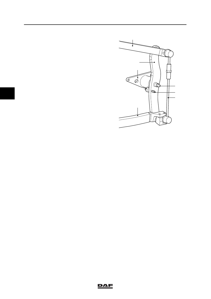
11. Loosen the lock nuts of the torque rod (5)

and adjust the length in such a way that the
gear lever shifting pattern is such that no
components are hit. Tighten the lock nuts.

12. Remove the dowel pin (A).

13. Check whether all gears can be engaged

without components being hit.

V300134

5

A

2

3

8

4

1

3

ǹ 0002

3

Removal and installation

MECHANICAL GEARBOX CONTROL (MGS)

3-1

3. REMOVAL AND INSTALLATION

3.1 REMOVAL AND INSTALLATION, GEAR LEVER LHD

Removal, gear lever LHD
1.

Disconnect the gear lever dust cover from
the cab floor inside the cab.

2.

Remove the shifting valve from the gear
lever. Mark the air lines, as necessary.

3.

Ensure that the gearbox is in neutral.

4.

Tilt the cab.

5.

Loosen the engine encapsulation and lower
it onto the engine.

6.

Remove the clamping bolt (12) and remove
the control rod (1) from the gear lever.

7.

Remove the fixing bolts from the base
plate (9) and remove the entire gear lever
unit from the cab floor.

V300135

B

10

90

°

9

12

11

1

3

ǹ 0002

3

MECHANICAL GEARBOX CONTROL (MGS)

Removal and installation

3-2

Installation, gear lever
1.

Before inserting the gear lever through the
hole in the cab floor, install the control
rod (1) onto the gear leaver and
hand-tighten the clamping bolt (12).

2.

Install the gear lever, including the guiding
pin (B), into the cab floor and tighten the
fixing bolts to the specified torque, see main
group “Technical Data”.

3.

Tighten the clamping bolt (12) to the
specified torque.

4.

Install the air pipes in the gear lever.

5.

Install the shifting valve onto the gear lever.

6.

Adjust the gearbox control, see chapter
“Checking and Adjusting”.

7.

Install the engine encapsulation by installing
the torque rod fixing bolts to the top of the
cab.

8.

Install the gear lever dust cover.

V300135

B

10

90

°

9

12

11

1

3

ǹ 0002

3

Removal and installation

MECHANICAL GEARBOX CONTROL (MGS)

3-3

3.2 REMOVAL AND INSTALLATION OF GEAR LEVER RHD

Removal, gear lever RHD
1.

Disconnect the gear lever dust cover from
the cab floor inside the cab.

2.

Remove the shifting valve from the gear
lever. Mark the air lines, as necessary.

3.

Ensure that the gearbox is in neutral.

4.

Tilt the cab.

5.

Loosen the engine encapsulation and lower
it onto the engine.

6.

Remove the clamping bolt (12) and remove
the control rod (1) from the gear lever.

7.

Remove the shift control cover at the
bottom of the cab.

8.

Remove the fixing bolts from the base
plates (9) and remove the entire gear lever,
including connecting rod and auxiliary
control, from the cab floor.

V300150

12

1

9

9

3

ǹ 0002


Content   ..  458  459  460  461   ..