Chrysler Sebring, Stratus sedan, Sebring Convertible. Manual - part 735


  Index      Chrysler     Chrysler Sebring, Stratus sedan, Sebring Convertible - service repair manual 2001-2007 year


Search            


Content   ..  733  734  735  736   ..


Chrysler Sebring, Stratus sedan, Sebring Convertible. Manual - part 735


REMOVAL

REMOVAL - AIR OUTLET

NOTE: Only the right outboard air outlet can be
removed individually for service replacement. The
other instrument panel air outlets are part of the
instrument cluster bezel and cannot be serviced
separately.

(1) Remove the right instrument panel trim bezel

(Refer to 23 - BODY/INSTRUMENT PANEL/IN-
STRUMENT PANEL TRIM - REMOVAL).

(2) Using a trim stick or another suitable wide

flat-bladed tool, gently pry out the air outlet barrel
from the instrument panel air outlet located on the
right outboard end of the instrument panel (Fig. 2).

(3) Remove the screws that secure the air outlet to

the right outboard end of the instrument panel and
remove the outlet.

REMOVAL - AIR OUTLET BARRELS

NOTE: The instrument panel air outlet barrels are
retained to the pivots within the air outlets by a
snap fit.

(1) Using a trim stick or another suitable wide

flat-bladed tool, gently pry on the air outlet barrel
until the barrel retainers release from the barrel piv-
ots of the air outlet housing (Fig. 3).

(2) Remove the air outlet barrel(s) from the instru-

ment panel air outlet(s) as required. If needed, use a
trim stick to help remove the barrels.

INSTALLATION

INSTALLATION - AIR OUTLET

NOTE: Only the right outboard air outlet can be
removed individually for service replacement. The
other instrument panel air outlets are part of the
instrument cluster bezel and cannot be serviced
separately.

(1) Position the air outlet onto the right outboard

end of the instrument panel.

(2) Install the screws that secure the air outlet to

the instrument panel. Tighten the screws to 2 N·m
(17 in. lbs.).

(3) Install the air outlet barrel into the air outlet

by gently pushing the barrel into the outlet until it
snaps firmly into position.

(4) Install the right instrument panel trim bezel

(Refer to 23 - BODY/INSTRUMENT PANEL/IN-
STRUMENT PANEL TRIM - INSTALLATION).

INSTALLATION - AIR OUTLET BARRELS

(1) Position the air outlet barrel(s) to the air out-

let(s) as required.

(2) Install the air outlet barrel onto the pivot shaft

on the right side of the air outlet.

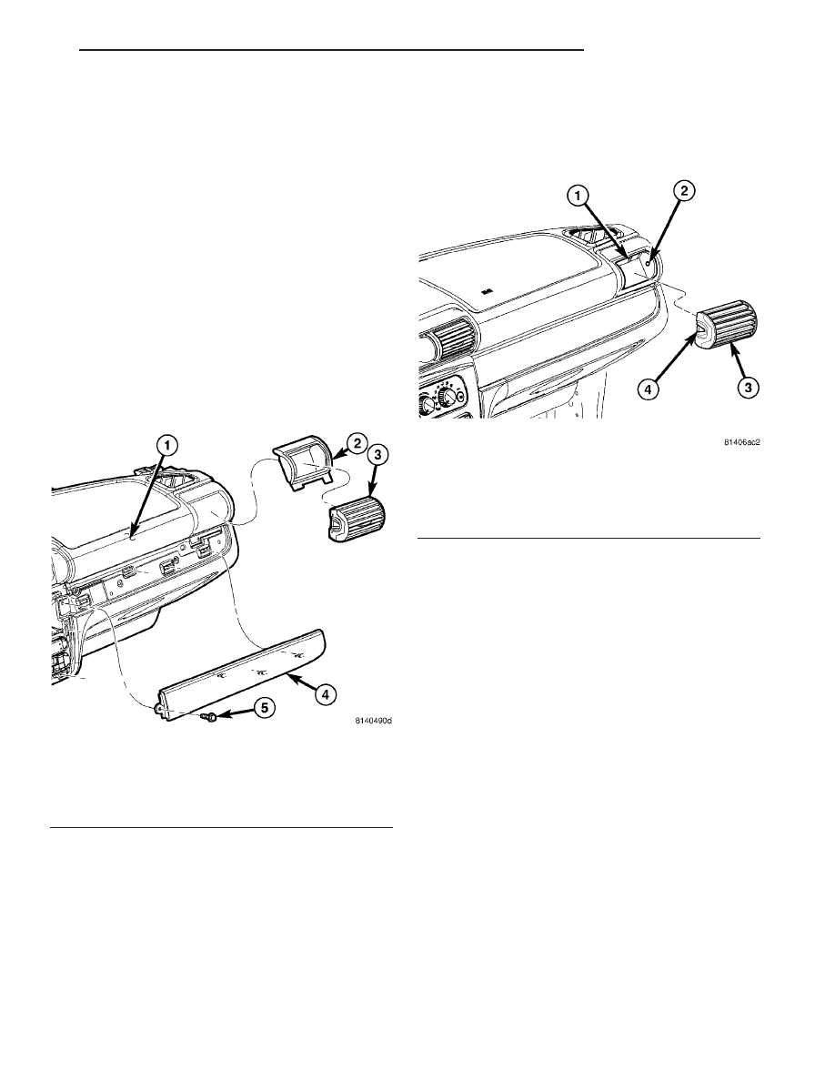
Fig. 2 Right Outboard IP Air Outlet

1 - INSTRUMENT PANEL
2 - AIR OUTLET
3 - AIR OUTLET BARREL
4 - RIGHT IP TRIM BEZEL
5 - SCREW

Fig. 3 Air Outlet Barrels

1 - AIR OUTLET HOUSING
2 - PIVOT SHAFT (2)
3 - AIR OUTLET BARREL (4)
4 - BARREL RETAINER (2)

JR

DISTRIBUTION

24 - 39

AIR OUTLETS (Continued)

(3) Gently push the air outlet barrel onto the pivot

shaft on the left side of the instrument panel air out-
let until it snaps into position on the pivot shaft.

BLOWER MOTOR

DESCRIPTION

The blower motor (Fig. 4) is a 12-volt, direct cur-

rent (DC) motor mounted within a plastic housing
with an integral wire harness connector and squirrel
cage-type blower wheel that is secured to the blower
motor shaft. The blower motor wheel is located in the
HVAC air inlet housing which is on the passenger
side end of the HVAC housing. The blower motor can
be accessed for service from underneath the instru-
ment panel.

OPERATION

The blower motor controls the velocity of air mov-

ing through the HVAC housing by spinning the
blower wheel within the HVAC air inlet housing at
the selected speed or, in the automatic temperature
control (ATC) system, at the selected or programmed
speed.

Blower motor speed for the MTC system is con-

trolled by regulating the blower motor ground path
through the blower motor resistor and through the
blower motor control located within the MTC A/C-
heater control. The blower motor will operate when-
ever the ignition switch is in the Run position and
the blower motor control in any position except Off.

For the ATC system, blower motor speed is con-

trolled by the body control module (BCM). The BCM
varies the duty cycle supplied by the blower motor
power module to a fixed frequency output (pulse
width modulation) as requested by the ATC blower
motor control (manual mode) or by sensor data (auto-
matic mode). The blower motor will operate when-
ever the ignition switch is in the Run position and
the A/C-heater control power is turned on.

The blower motor and blower motor wheel are fac-

tory balanced and cannot be adjusted or repaired. If
faulty or damaged, the blower motor and blower
wheel must be replaced as an assembly.

DIAGNOSIS AND TESTING

BLOWER MOTOR

WARNING: On vehicles equipped with airbags, dis-
able the airbag system before attempting any steer-
ing wheel, steering column, or instrument panel
component diagnosis or service. Disconnect and
isolate the negative battery (ground) cable, then
wait two minutes for the airbag system capacitor to
discharge before performing further diagnosis or
service. Failure to take the proper precautions
could result in accidental airbag deployment and
possible personal injury or death.

NOTE: For circuit descriptions and diagrams, refer
to Air Conditioning/Heater in Group 8W - Wiring
Diagrams.

OPERATION

Possible causes of an inoperative blower motor

include:

• Faulty fuse

• Faulty blower motor resistor or power module

(depending on application)

• Faulty blower motor switch

• Faulty mode control switch

• Faulty blower motor

• Faulty blower motor circuit wiring or wire har-

ness connectors

Possible causes of the blower motor not operating

in all speeds include:

• Faulty fuse

• Faulty blower motor resistor or power module

(depending on application)

• Faulty blower motor switch

• Faulty blower motor

• Faulty blower motor circuit wiring or wire har-

ness connectors

Fig. 4 Blower Motor - Description

1 - BLOWER MOTOR
2 - WIRE HARNESS CONNECTOR
3 - BLOWER WHEEL
4 - BLOWER MOTOR SHAFT

24 - 40

DISTRIBUTION

JR

AIR OUTLETS (Continued)

VIBRATION

Possible causes of blower motor vibration include:
• Improper blower motor mounting

• Improper blower wheel mounting

• Deformed blower wheel

• Out of balance blower wheel due to foreign

material in the wheel

• Faulty blower motor

NOISE

To determine if the blower motor is the source of

the noise, simply switch the blower motor from Off to
On. To verify that the blower motor is the source of
the noise, unplug the blower motor wire harness con-
nector and operate the heating-A/C system. If the
noise goes away, possible causes include:

• Foreign material in the HVAC air inlet housing

• Improper blower motor mounting

• Improper blower wheel mounting

• Faulty blower motor

REMOVAL

WARNING: On vehicles equipped with airbags, dis-
able the airbag system before attempting any steer-
ing wheel, steering column, or instrument panel
component diagnosis or service. Disconnect and
isolate the negative battery (ground) cable, then
wait two minutes for the airbag system capacitor to
discharge before performing further diagnosis or
service. This is the only sure way to disable the air-
bag system. Failure to take the proper precautions
could result in accidental airbag deployment and
possible personal injury or death.

(1) Disconnect and isolate the negative battery

cable.

(2) Remove the instrument panel silencer from the

passenger side of the instrument panel (Refer to 23 -
BODY/INSTRUMENT

PANEL/INSTRUMENT

PANEL SILENCER - REMOVAL)

(3) Disconnect the wire harness connector from the

blower motor (Fig. 5).

(4) Remove the three screws that secure the

blower motor to the HVAC housing.

(5) Remove the blower motor from the HVAC hous-

ing by rotating and tilting the motor as needed for
clearance of the blower wheel.

INSTALLATION

(1) Position the blower motor into the HVAC hous-

ing.

(2) Install the three screws that secure the blower

motor to the HVAC housing. Tighten the screws to 2
N·m (17 in. lbs.).

(3) Connect the wire harness connector to the

blower motor.

(4) Install the instrument panel silencer onto the

passenger side of the instrument panel (Refer to 23 -
BODY/INSTRUMENT

PANEL/INSTRUMENT

PANEL SILENCER - INSTALLATION)

(5) Reconnect the negative battery cable.

Fig. 5 HVAC Blower Motor - Typical

1 - BLOWER WHEEL
2 - BLOWER MOTOR

JR

DISTRIBUTION

24 - 41

BLOWER MOTOR (Continued)

DEFROSTER DUCT

REMOVAL

(1) Remove the instrument panel top pad (Refer to

23 - BODY/INSTRUMENT PANEL/INSTRUMENT
PANEL TOP PAD - REMOVAL).

(2) Pull the defroster duct straight up to discon-

nect it from the top of the HVAC housing (Fig. 6).

(3) Remove the defroster duct from instrument

panel.

INSTALLATION

(1) Position the defroster duct onto the top of the

instrument panel.

(2) Install the defroster duct to the HVAC housing

through the opening in the instrument panel. Make
sure that the defroster duct is fully engaged to the
HVAC housing.

(3) Install the instrument panel top pad (Refer to

23 - BODY/INSTRUMENT PANEL/INSTRUMENT
PANEL TOP PAD - INSTALLATION).

FLOOR DISTRIBUTION DUCT

REMOVAL

WARNING: On vehicles equipped with airbags, dis-
able the airbag system before attempting any steer-
ing wheel, steering column, or instrument panel
component diagnosis or service. Disconnect and
isolate the battery negative (ground) cable, then
wait two minutes for the airbag system capacitor to
discharge before performing further diagnosis or

service. This is the only sure way to disable the air-
bag system. Failure to take the proper precautions
could result in an accidental airbag deployment and
possible personal injury or death.

(1) Remove the HVAC housing from the vehicle

(Refer to 24 - HEATING & AIR CONDITIONING/
DISTRIBUTION/HVAC HOUSING - REMOVAL).

(2) Remove the screws that secure the floor distri-

bution duct to the bottom of the HVAC housing (Fig.
7).

(3) Remove the floor distribution duct from the

HVAC housing.

INSTALLATION

(1) Position the floor distribution duct to the bot-

tom of the HVAC housing.

(2) Install the screws that secure the floor distri-

bution duct to the HVAC housing. Tighten the screws
to 2 N·m (17 in. lbs.).

(3) Install the HVAC housing (Refer to 24 - HEAT-

ING & AIR CONDITIONING/DISTRIBUTION/HVAC
HOUSING - INSTALLATION).

HVAC HOUSING

REMOVAL

WARNING: Refer to the applicable warnings and
cautions for this system before performing the fol-
lowing operation (Refer to 24 - HEATING & AIR
CONDITIONING/PLUMBING - WARNINGS) and (Refer
to 24 - HEATING & AIR CONDITIONING/PLUMBING -
CAUTIONS). Failure to follow the warnings and cau-
tions could result in possible personal injury or
death.

Fig. 6 Defroster Duct

1 - DEFROSTER DUCT
2 - INSTRUMENT PANEL

Fig. 7 Floor Distribution Duct

1 - FLOOR DISTRIBUTION DUCT
2 - MODE DOOR ACTUATOR
3 - BLEND DOOR ACTUATOR
4 - HVAC HOUSING

24 - 42

DISTRIBUTION

JR


Content   ..  733  734  735  736   ..