Chrysler Sebring, Stratus sedan, Sebring Convertible. Manual - part 733


  Index      Chrysler     Chrysler Sebring, Stratus sedan, Sebring Convertible - service repair manual 2001-2007 year


Search            


Content   ..  731  732  733  734   ..


Chrysler Sebring, Stratus sedan, Sebring Convertible. Manual - part 733


MODE DOOR ACTUATOR

DESCRIPTION

The mode door actuator (Fig. 39) is a reversible,

12-volt direct current (DC), servo motor which mechan-
ically positions the mode-air doors. The mode door
actuator is located on the bottom of the HVAC housing.

The mode door actuator is interchangeable with the

actuator for the blend-air door. Each actuator is con-
tained within an identical black molded plastic housing
with an integral wire connector receptacle. Each actua-
tor also has an identical output shaft with splines that
connect it to its respective door linkage and three inte-
gral mounting tabs that allow the actuator to be
secured to the HVAC housing. The mode door actuator
requires mechanical indexing to the mode door linkage.

OPERATION

The mode door actuator is connected to the body

control module (BCM) through the vehicle electrical
system by a dedicated five-wire lead and connector of
the HVAC wire harness. The mode door actuator can
move the panel-air door and the floor/defrost-air door
(mode-air doors) in two directions. A potentiometer
within the actuator allows the BCM to know the
exact position of the mode-air doors at all times.

The mode door actuator can be diagnosed using a

DRBIII

t scan tool. Refer to Body Diagnostic Proce-

dures for more information.

The mode door actuator cannot be adjusted or

repaired and, if faulty or damaged, it must be replaced.

REMOVAL

WARNING: On vehicles equipped with airbags, disable
the airbag system before attempting any steering
wheel, steering column, or instrument panel component
diagnosis or service. Disconnect and isolate the nega-
tive battery (ground) cable, then wait two minutes for
the airbag system capacitor to discharge before per-
forming further diagnosis or service. This is the only
sure way to disable the airbag system. Failure to take
the proper precautions could result in accidental airbag
deployment and possible personal injury or death.

(1) Disconnect and isolate the negative battery cable.
(2) Remove the left lower silencer panel and

instrument panel trim cover (Refer to 23 - BODY/IN-
STRUMENT PANEL/INSTRUMENT PANEL TRIM -
REMOVAL).

(3) Remove the push pin that secures the kick

shield to the instrument panel near the accelerator
pedal and remove the shield.

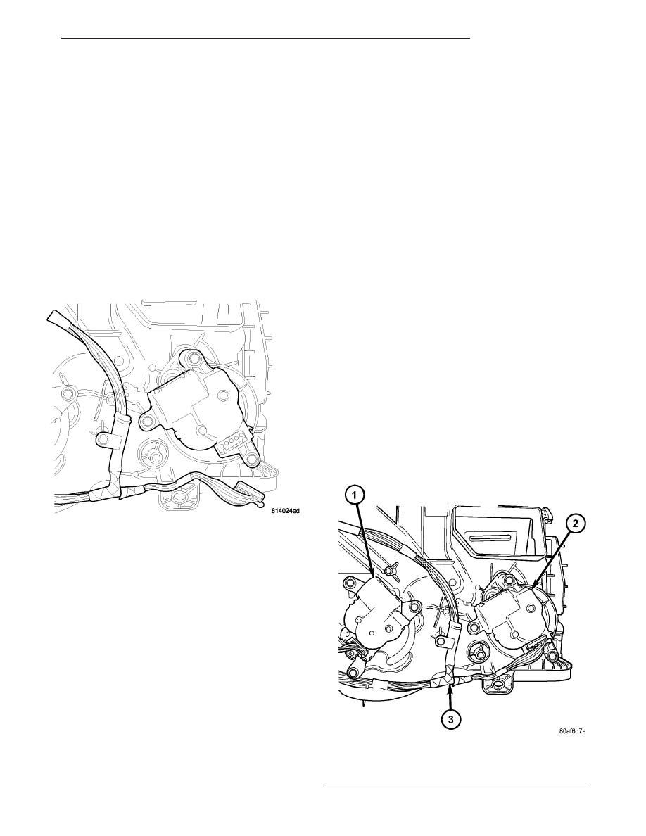
(4) Remove the three screws that secure the mode

door actuator to the bottom of the HVAC housing
(Fig. 40).

NOTE: When removing the actuator, note the posi-
tion of the actuator shaft and its respective linkage
for installation reference.

(5) Remove the mode door actuator from the HVAC

housing and disconnect the HVAC wire harness con-
nector from the actuator.

Fig. 39 Mode Door Actuator

Fig. 40 Mode Door Actuator

1 - BLEND DOOR ACTUATOR
2 - MODE DOOR ACTUATOR
3 - HVAC WIRE HARNESS

JR

CONTROLS

24 - 31

INSTALLATION

(1) Install the mode door actuator onto the bottom

of the HVAC housing. If necessary, rotate the actua-
tor slightly to align the splines on the actuator out-
put shaft with those on the mode door cam (Fig. 41).

(2) Install the three screws that secure the mode

door actuator to the HVAC housing. Tighten the
screws to 2 N·m (17 in. lbs.).

(3) Connect the HVAC wire harness connector to

the mode door actuator.

(4) Install the kick shield and the push-pin that

secures the kick shield to the instrument panel.

(5) Install the left lower instrument panel trim

cover and silencer panel (Refer to 23 - BODY/IN-
STRUMENT PANEL/INSTRUMENT PANEL TRIM -
INSTALLATION).

(6) Reconnect the negative battery cable.

BLOWER MOTOR POWER
MODULE

DESCRIPTION

A blower motor power module (Fig. 42) is used on

this model when it is equipped with the optional
automatic temperature control (ATC) heating-A/C
system. Models equipped with the standard manual
temperature control (MTC) heating-A/C system use a
blower motor resistor, instead of the blower motor

power module (Refer to 24 - HEATING & AIR CON-
DITIONING/CONTROLS/BLOWER MOTOR RESIS-
TOR - DESCRIPTION).

The blower motor power module is mounted to the

bottom of the HVAC housing, directly behind the
glove box. The blower motor power module consists of
a molded plastic mounting plate with two integral
connector receptacles. Concealed behind the mount-
ing plate is the power module electronic circuitry and
a large finned heat sink. The blower motor power
module is accessed for service by removing the pas-
senger side silencer panel.

OPERATION

The blower motor power module is connected to the

vehicle electrical system through a dedicated lead
and connector of the HVAC wire harness. A second
connector receptacle receives a wire lead connector
from the blower motor. The blower motor power mod-
ule allows the automatic temperature control (ATC)
heating-A/C system to calculate and provide infi-
nitely variable blower motor speeds based upon
either manual blower switch input or the ATC pro-
gramming strategy. The body control module (BCM)
receives the desired blower speed input from the A/C-
heater control and then process the control signal to
change or maintain the desired blower speed.

The blower motor power module is diagnosed using

a DRBIII

t scan tool. Refer to Body Diagnostic Proce-

dures.

The blower motor power cannot be adjusted or

repaired and, if faulty or damaged, it must be
replaced.

Fig. 41 Mode Door Actuator Spline

1 - ACTUATOR SPLINE
2 - DOOR CAM SPLINE
3 - MODE DOOR ACTUATOR

Fig. 42 Blower Motor Power Module

1 - BLOWER MOTOR POWER MODULE
2 - HEAT SINK

24 - 32

CONTROLS

JR

MODE DOOR ACTUATOR (Continued)

REMOVAL

WARNING: On vehicles equipped with airbags, dis-
able the airbag system before attempting any steer-
ing wheel, steering column, or instrument panel
component diagnosis or service. Disconnect and
isolate the negative battery (ground) cable, then
wait two minutes for the airbag system capacitor to
discharge before performing further diagnosis or
service. This is the only sure way to disable the air-
bag system. Failure to take the proper precautions
could result in accidental airbag deployment and
possible personal injury or death.

WARNING: The heat sink for the blower motor
power module may get very hot during normal
operation. If the blower motor was turned on prior
to servicing the blower motor power module, wait
five minutes to allow the heat sink to cool before
performing diagnosis or service. Failure to take this
precaution can result in possible personal injury.

(1) Disconnect and isolate the battery negative cable.
(2) Remove the silencer panel from right side of

the instrument panel (Refer to 23 - BODY/INSTRU-
MENT PANEL/RIGHT IP SILENCER PANEL -
REMOVAL).

(3) Disconnect the two wire harness connectors

from the blower motor power module located at the
bottom of the HVAC housing (Fig. 43).

(4) Remove the two screws that secure the blower

motor power module to the HVAC housing and
remove the power module.

INSTALLATION

(1) Position the blower motor power module into

the bottom of the HVAC housing.

(2) Install the two screws that secure the blower

motor power module to the HVAC housing. Tighten
the screws to 2 N·m (17 in. lbs.).

(3) Connect the two wire connectors to the blower

motor power module.

(4) Install the silencer panel to the right side of

the instrument panel (Refer to 23 - BODY/INSTRU-
MENT PANEL/RIGHT IP SILENCER PANEL -
INSTALLATION).

(5) Reconnect the negative battery cable.

RECIRCULATION DOOR
ACTUATOR

DESCRIPTION

The recirculation door actuator (Fig. 44) is a

reversible 12-volt direct current (DC) servo motor.

The single recirculation door actuator is located on
the passenger side end of the HVAC housing, on the
air inlet housing. The recirculation door actuator is
mechanically connected to the recirculation-air door.

The recirculation door actuator is not interchange-

able with the actuators for the blend or mode-air
doors. The recirculation door actuator is contained
within a black molded plastic housing with an inte-
gral wire connector receptacle. The recirculation door
actuator has a output shaft with splines that connect
it to the recirculation-air door linkage and three inte-
gral mounting tabs that allow the actuator to be
secured to the HVAC air inlet housing. The recircu-
lation door actuator requires mechanical indexing to
the recirculation-air door.

OPERATION

The recirculation door actuator is connected to the

body control module (BCM) through the vehicle elec-
trical system by a dedicated two-wire lead and con-
nector of the HVAC wire harness. The recirculation
door actuator can move the recirculation door in two
directions. When the BCM pulls the voltage on one
side of the motor connection high and the other con-
nection low, the recirculation air door will move in
one direction. When the BCM reverses the polarity of
the voltage to the motor, the recirculation air door
moves in the opposite direction. When the BCM
makes the voltage to both connections high or both
connections low, the recirculation air door stops and
will not move. The BCM operates the recirculation
door actuator on a timed actauation period.

Fig. 43 Blower Motor Power Module

1 - WIRE HARNESS CONNECTORS
2 - BLOWER MOTOR POWER MODULE
3 - SCREWS
4 - HVAC HOUSING

JR

CONTROLS

24 - 33

BLOWER MOTOR POWER MODULE (Continued)

The recirculation door actuator can be diagnosed

using a DRBIII

t scan tool. Refer to Body Diagnostic

Procedures for more information.

The recirculation door actuator cannot be adjusted

or repaired and, if faulty or damaged, it must be
replaced.

REMOVAL

WARNING: On vehicles equipped with airbags, dis-
able the airbag system before attempting any steer-
ing wheel, steering column, or instrument panel
component diagnosis or service. Disconnect and
isolate the battery negative (ground) cable, then
wait two minutes for the airbag system capacitor to
discharge before performing further diagnosis or
service. This is the only sure way to disable the air-
bag system. Failure to take the proper precautions
could result in accidental airbag deployment and
possible personal injury or death.

(1) Disconnect and isolate the negative battery

cable.

(2) Remove the instrument panel from the vehicle

(Refer to 23 - BODY/INSTRUMENT PANEL/IN-
STRUMENT PANEL ASSEMBLY - REMOVAL).

(3) Disconnect the HVAC wire harness connector

from the recirculation door actuator (Fig. 45).

(4) Remove the three screws that secure the recir-

culation door actuator to the HVAC air inlet housing.

NOTE: When removing the actuator, note the posi-
tion of the actuator shaft and its respective linkage
for installation reference.

(5) Remove the recirculation door actuator from

the HVAC air inlet housing.

Fig. 44 Recirculation Door Actuator

1 - RECIRCULATION-AIR DOOR ACTUATOR
2 - WIRE CONNECTOR RECEPTACLE
3 - OUTPUT SHAFT
4 - MOUNTING TAB (3)

Fig. 45 Recirculation Door Actuator

1 - HVAC AIR INLET HOUSING
2 - RECIRCULATION DOOR ACTUATOR

24 - 34

CONTROLS

JR

RECIRCULATION DOOR ACTUATOR (Continued)


Content   ..  731  732  733  734   ..