Chrysler Sebring, Stratus sedan, Sebring Convertible. Manual - part 732


  Index      Chrysler     Chrysler Sebring, Stratus sedan, Sebring Convertible - service repair manual 2001-2007 year


Search            


Content   ..  730  731  732  733   ..


Chrysler Sebring, Stratus sedan, Sebring Convertible. Manual - part 732


OPERATION

The blower motor resistor is connected to the vehi-

cle electrical system through a dedicated wire lead
and connector of the HVAC wire harness. The blower
motor resistor has multiple resistor circuits, each of
which will reduce the current flow through the
blower motor to change the blower motor speed.

The blower motor switch in the MTC heating-A/C

system directs the ground path for the blower motor
through the correct resistor circuit to obtain the
selected speed. With the blower motor control in the
lowest speed position, the ground path for the blower
motor is applied through all of the resistor circuits.
Each higher speed selected with the blower motor
control

applies

the

blower

motor

ground

path

through fewer of the resistor circuits, increasing the
blower motor speed.

The blower motor resistor cannot be adjusted or

repaired and, if faulty or damaged, it must be
replaced.

DIAGNOSIS AND TESTING

BLOWER MOTOR RESISTOR

WARNING: On vehicles equipped with airbags, dis-
able the airbag system before attempting any steer-
ing wheel, steering column, or instrument panel
component diagnosis or service. Disconnect and
isolate the negative battery (ground) cable, then
wait two minutes for the airbag system capacitor to
discharge before performing further diagnosis or

service. This is the only sure way to disable the air-
bag system. Failure to take the proper precautions
could result in accidental airbag deployment and
possible personal injury or death.

NOTE: For circuit descriptions and diagrams, refer
to the appropriate wiring information. The wiring
information includes wiring diagrams, proper wire
and connector repair procedures, further details on
wire harness routing and retention, as well as pin-
out and location views for the various wire harness
connectors, splices and grounds.

(1) Disconnect and isolate the negative battery

cable.

(2) Disconnect the wire harness connector from the

blower motor resistor (Refer to 24 - HEATING & AIR
CONDITIONING/CONTROLS/BLOWER

MOTOR

RESISTOR - REMOVAL).

(3) Using

an

ohmmeter,

check

for

continuity

between all of the blower motor resistor terminals. In
each case there should be continuity. If OK, repair
the wire harness circuits between the blower motor
switch and the blower motor resistor or blower motor
as required. If not OK, replace the faulty blower
motor resistor.

REMOVAL

WARNING: On vehicles equipped with airbags, dis-
able the airbag system before attempting any steer-
ing wheel, steering column, or instrument panel
component diagnosis or service. Disconnect and
isolate the battery negative (ground) cable, then
wait two minutes for the airbag system capacitor to
discharge before performing further diagnosis or
service. This is the only sure way to disable the air-
bag system. Failure to take the proper precautions
could result in accidental airbag deployment and
possible personal injury or death.

WARNING: The blower motor resistor may get very
hot during normal operation. If the blower motor
was turned on prior to servicing the blower motor
resistor, wait five minutes to allow the resistor to
cool before performing diagnosis or service. Failure
to take this precaution can result in personal injury.

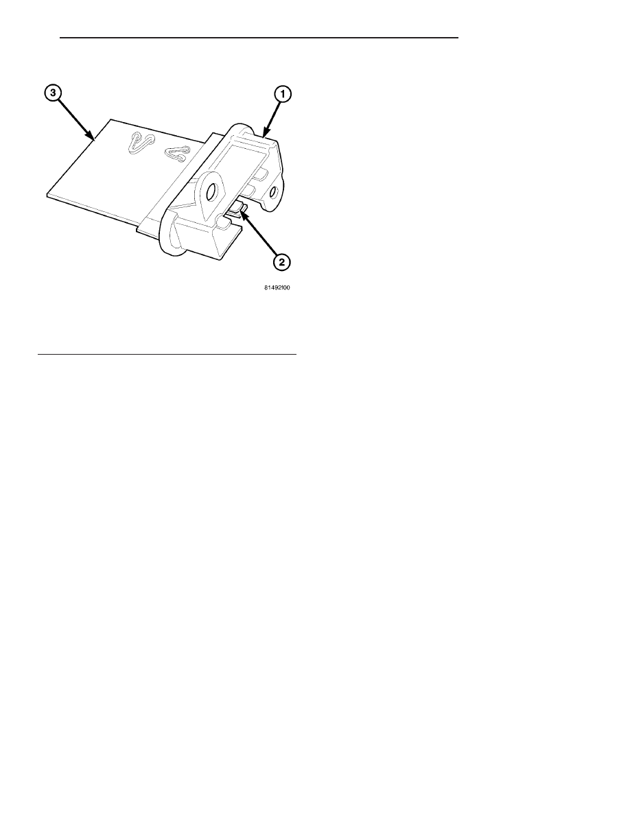
Fig. 32 Blower Motor Resistor

1 - MOUNTING PLATE
2 - WIRE HARNESS CONNECTOR
3 - RESISTOR CIRCUIT BOARD

JR

CONTROLS

24 - 27

BLOWER MOTOR RESISTOR (Continued)

(1) Disconnect and isolate the negative battery

cable.

(2) Remove the silencer panel from right side of

the instrument panel (Refer to 23 - BODY/INSTRU-
MENT PANEL/RIGHT IP SILENCER PANEL -
REMOVAL).

(3) Disconnect the wire harness connector from the

blower motor resistor located on the bottom of the
HVAC housing (Fig. 33).

(4) Remove the two screws that secure the blower

motor resistor to the HVAC housing and remove the
resistor.

INSTALLATION

(1) Position the blower motor resistor into the bot-

tom of the HVAC housing.

(2) Install the two screws that secure the blower

motor resistor to the HVAC housing. Tighten the
screws to 2 N·m (17 in. lbs.).

(3) Connect the wire harness connector to the

blower motor resistor.

(4) Install the silencer panel to the right side of

the instrument panel (Refer to 23 - BODY/INSTRU-
MENT PANEL/RIGHT IP SILENCER PANEL -
INSTALLATION).

(5) Reconnect the negative battery cable.

EVAPORATOR TEMPERATURE
SENSOR

DESCRIPTION

The evaporator temperature sensor (Fig. 34) is a

thermistor with a sensing probe that is inserted
between the fins of the A/C evaporator at its coldest
point. The evaporator temperature sensor prevents
condensate water on the A/C evaporator from freez-
ing and obstructing A/C system air flow. The sensor
probe is filled with a special silicone-based thermal
grease. Two terminals within a molded plastic con-
nector receptacle on the sensor connect it to the vehi-
cle electrical system through a wire lead and
connector of the HVAC wire harness.

OPERATION

The evaporator temperature sensor is a thermistor

that operates on a 5-volt reference signal sent out by
the body control module (BCM). The evaporator tem-
perature sensor connects to the BCM through a two-
wire lead and connector of the HVAC wire harness.
The evaporator temperature sensor monitors the
temperature of the A/C evaporator and changes its
internal resistance in response to changes in the
evaporator temperature. In turn, the change in the
sensors internal resistance changes the reference sig-
nal voltage read by the BCM.

The BCM uses the reference signal voltage as an

indication that conditions are correct to request A/C
operation, should the operator (manually) or the A/C-
heater control (automatically) so desire this function.
In turn, the BCM broadcasts the A/C request on the
programmable communications interface (PCI) bus,
where it is read and processed by the powertrain con-
trol module (PCM). The PCM will check engine cool-

Fig. 33 Blower Motor Resistor

1 - BLOWER MOTOR RESISTOR
2 - SCREW (2)
3 - WIRE HARNESS CONNECTOR
4 - HVAC HOUSING

Fig. 34 Evaporator Temperature Sensor

1 - SENSING PROBE
2 - WIRE HARNESS CONNECTOR

24 - 28

CONTROLS

JR

BLOWER MOTOR RESISTOR (Continued)

ant

temperature

and

refrigerant

pressure

temperature before activating the A/C compressor
clutch.

The evaporator temperature sensor is diagnosed

using a DRBIII

t scan tool. Refer to the appropriate

diagnostic information.

The evaporator temperature sensor cannot be

adjusted or repaired and, if faulty or damaged, it
must be replaced.

REMOVAL

(1) Disconnect the negative battery cable.
(2) Remove the glove compartment door.
(3) Remove the blower motor from the HVAC hous-

ing (Refer to 24 - HEATING & AIR CONDITION-
ING/DISTRIBUTION/BLOWER

MOTOR

-

REMOVAL).

(4) If equipped with the MTC heating-A/C system,

remove the blower motor resistor from the HVAC
housing (Refer to 24 - HEATING & AIR CONDI-
TIONING/CONTROLS/BLOWER

MOTOR

RESIS-

TOR - REMOVAL).

(5) Reach through the glove compartment door

opening and disconnect the evaporator temperature
sensor wiring connector.

(6) Using a flat blade pry tool, disengage the lock-

ing tab on the access plate of the evaporator temper-
ture sensor. Turn the access plate clockwise one-
quarter turn and push the access plate inside of the
HVAC housing (Fig. 35), then orientate the plate in
such a way that it can be removed from the HVAC
housing.

NOTE: To remove the evaporator temperature sen-
sor probe, look through the access plate hole in the
HVAC housing and reach up through the blower
motor opening.

(7) Remove the evaporator temperature sensor

probe from the A/C evaporator (Fig. 36).

INSTALLATION

NOTE: The A/C evaporator is manufactured with
three holes for evaporator temperature sensor
probe insertion. Always insert the probe into the
uppermost hole.

(1) Install

the

evaporator

temperature

sensor

probe into the A/C evaporator.

(2) Install the access plate to the HVAC housing.
(3) Connect the wire harness connector to the

evaporator temperature sensor.

(4) If equipped with the MTC heating-A/C system,

install the blower motor resistor (Refer to 24 - HEAT-
ING & AIR CONDITIONING/CONTROLS/BLOWER
MOTOR RESISTOR - INSTALLATION).

(5) Install the blower motor (Refer to 24 - HEAT-

ING

&

AIR

CONDITIONING/DISTRIBUTION/

BLOWER MOTOR - INSTALLATION).

(6) Install the glove compartment door.
(7) Reconnect the negative battery cable.

IN-CAR TEMPERATURE
SENSOR

DESCRIPTION

The in-car temperature sensor is used in the auto-

matic temperature control (ATC) heating-A/C system
only. The in-car temperature sensor returns electrical
signals to the body control module (BCM). The in-car
temperature sensor is made up of two parts. One
part is the in-car sensor aspirator motor assembly,
and the second part is a temperature thermistor. The
in-car sensor aspirator motor assembly attaches to

Fig. 35 Evaporator Temperature Sensor

1 - ACCESS PLATE

Fig. 36 Remove Probe

1 - EVAPORATOR TEMPERATURE SENSOR PROBE

JR

CONTROLS

24 - 29

EVAPORATOR TEMPERATURE SENSOR (Continued)

the back of the A/C-heater control (Fig. 37). This
assembly has a small fan and a motor which draws
air from the passenger compartment through the
intake on the front of the A/C-heater control and past
the in-car sensor thermistor which is located inside
of the A/C-heater control.

OPERATION

Air is drawn from the passenger compartment by

the aspirator motor, and flows over the in-car tem-
perature sensor thermisto. The thermistor changes
resistance with air temperature. The BCM measures
this resistance and calculates the temperature of the
air drawn into the A/C-heater control. The ATC sys-
tem then makes adjustments to maintain the opti-
mum passenger compartment comfort. Refer to the
In-Car Sensor Aspirator Motor Operation table for
when the aspirator motor is operating.

IN-CAR SENSOR ASPIRATOR MOTOR

OPERATION

CONDITION

MOTOR OPERATION

IGNITION SWITCH IS
ON

Motor always operates,
even when atc control
head

9

off

9

button is

pushed.

VEHICLE IS DRIVEN,
THEN THE IGNITION
SWITCH IS TURNED
OFF

Motor turns off when the
ignition switch is turned
off.

VEHICLE DOOR IS
OPENED, AND LEFT
OPEN, WITHOUT
TURNING ON THE
IGNITION SWITCH

Motor will turn on, and
then turn off
approximately 2 minutes
from the time the door
was opened.

VEHICLE DOOR IS
OPENED, AND THEN
CLOSED, WITHOUT
TURNING ON THE
IGNITION SWITCH

Motor will turn on, and
then turn off
approximately 2 minutes
after the door was
closed.

The in-car temperature sensor thermistor and aspi-

rator motor are part of the A/C-heater control and
cannot serviced separately. If faulty or damaged, the
A/C-heater control must be replaced.

DIAGNOSIS AND TESTING

IN-CAR TEMPERATURE SENSOR ASPIRATOR
MOTOR

(1) Perform the air flow test to check aspirator

motor operation.

(a) Turn the ignition switch to the ON position

and push the OFF button to stop the heater-A/C
system airflow. This will make it easier to observe
the paper in step b.

(b) Place a small piece of newspaper in front of

the aspirator motor opening on the A/C-heater con-
trol. If the paper sticks to the opening, the aspira-
tor motor is operating properly. The piece of paper
should be only large enough to cover the grille
opening (Fig. 38).
(2) If the paper does not stick to the opening,

check the electrical connections at the back of the
A/C-heater control. If connections are OK, replace the
A/C-heater control.

Fig. 37 ATC In-Car Temperature Sensor

1 - IN-CAR TEMPERATURE SENSOR

Fig. 38 ATC In-Car Temperature Sensor

1 - GRILLE OPENING

24 - 30

CONTROLS

JR

IN-CAR TEMPERATURE SENSOR (Continued)


Content   ..  730  731  732  733   ..