Chrysler Sebring, Stratus sedan, Sebring Convertible. Manual - part 684


  Index      Chrysler     Chrysler Sebring, Stratus sedan, Sebring Convertible - service repair manual 2001-2007 year


Search            


Content   ..  682  683  684  685   ..


Chrysler Sebring, Stratus sedan, Sebring Convertible. Manual - part 684


INSTALLATION

NOTE: Before installing a new motor or the original
motor ensure that the sunroof glass panel is in the
FULLY CLOSED POSITION. If sunroof glass panel is
not in the FULLY CLOSED POSITION (Refer to 23 -
BODY/SUNROOF/DRIVE MOTOR - ADJUSTMENTS).
If the original drive motor or new drive motor is not
in the CLOSED POSITION (Refer to 23 - BODY/SUN-
ROOF/DRIVE MOTOR - ADJUSTMENTS). A new
drive motor comes in the PARK POSITION, but if
the drive motor not in the fully closed position
(Refer to 23 - BODY/SUNROOF/DRIVE MOTOR -
ADJUSTMENTS).

(1) Ensure that sunroof module is in the FULLY

closed position before mounting the motor. If not in
the fully closed position (Refer to 23 - BODY/SUN-
ROOF/DRIVE MOTOR - ADJUSTMENTS).

(2) To time the drive motor (Refer to 23 - BODY/

SUNROOF/DRIVE MOTOR - ADJUSTMENTS).

(3) Place drive motor into position on the sunroof

housing and install attaching screws.

(4) Connect drive motor, and control switch wire

connectors.

(5) Test sunroof drive motor operation, adjust as

necessary (Refer to 23 - BODY/SUNROOF/DRIVE
MOTOR - ADJUSTMENTS).

(6) Install sunroof glass panel (Refer to 23 -

BODY/SUNROOF/GLASS

PANEL

-

INSTALLA-

TION).

(7) Verify sunroof operation and alignment, and

adjust as necessary. (Refer to 23 - BODY/SUNROOF/
GLASS PANEL - ADJUSTMENTS).

(8) Installing the headliner (Refer to 23 - BODY/

INTERIOR/HEADLINER - INSTALLATION).

(9) Install sunroof opening trim lace. (Refer to 23 -

BODY/SUNROOF/OPENING TRIM LACE - INSTAL-
LATION).

ADJUSTMENTS

ADJUSTMENT

DRIVE MOTOR

NOTE: The timing of both the drive motor and the
sunroof module play a critical roles in the proper
function of the sunroof. The sunroof assembly
come in the proper position. As long as the motor
is not has not been removed. If the drive motor is
removed and cycled the motor will have to be
Timed. If the sunroof glass panel has been moved
from

the

park

position

with

the

drive

motor

removed (Refer to 23 - BODY/SUNROOF/GLASS
PANEL - ADJUSTMENTS).

(1) With drive motor removed from the sunroof

assembly check the time of the drive motor.

(2) Plug the wire connectors to the drive motor. Do

not attach motor to sunroof assembly.

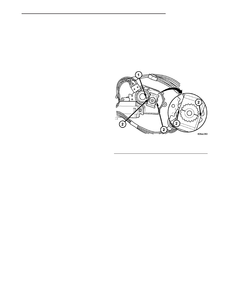
(3) Turn ignition switch to the accessory position,

tap the drive motor open position switch until the
motor timing mark align up straight across (Fig. 2).

(4) Install drive motor. (Refer to 23 - BODY/SUN-

ROOF/DRIVE MOTOR - INSTALLATION).

SUNROOF MODULE

NOTE: If the drive motor is removed and the sun-
roof glass or cables are moved the sunroof module
will have to be timed.

(1) With the drive motor removed.
(2) Remove sunroof glass panel (Refer to 23 -

BODY/SUNROOF/GLASS PANEL - REMOVAL).

(3) Now place both right and left arms in the

closed position. Using a screwdriver, push the plastic
cable all the way forward in the track until the glass
mounting arm drops into the closed position.

(4) Repeat this on the other side.
(5) To verify correct timing, there is an 1/8 inch

hole in the cable ramp that must be aligned with the
front glass mounting screw hole.

(6) Using an awl, verify alignment of both right

and left timing holes. The tracks will now be timed
to the fully closed position.

(7) With the drive motor in the fully closed posi-

tion. Install drive motor (Refer to 23 - BODY/SUN-
ROOF/DRIVE MOTOR - INSTALLATION).

Fig. 2 Sunroof Drive Motor Timing

1 - HOLE
2 - TIMING MARKS

JR

SUNROOF

23 - 133

SUNROOF DRIVE MOTOR (Continued)

SUNROOF GLASS PANEL

REMOVAL

(1) Slide sunshade rearward to the open position.
(2) Move the glass panel to the vent position.
(3) Remove the glass panel screws on each side

(Fig. 3).

(4) Lift off glass panel and remove from vehicle.

INSTALLATION

(1) Position glass panel on to mechanism.
(2) Start the six attaching screws.
(3) Close glass.
(4) Center glass in opening by running a business

card around the glass.

(5) Adjust front height of glass, just below roof

panel.

(6) Tighten front two screws.
(7) Adjust rear height of glass, just above roof

panel.

(8) Tighten remaining screws.
(9) Verify sunroof operation and alignment. Check

fit and adjust as necessary, (Refer to 23 - BODY/
SUNROOF/GLASS PANEL - DESCRIPTION).

ADJUSTMENTS

ADJUSTMENT

(1) Move the sunshade rearward to the open posi-

tion.

(2) Move the sunroof glass panel to the fully closed

position.

(3) Loosen the forward and center screws on each

side enough to make the front adjustment.

(4) Adjust the front of the sunroof glass panel 1

mm (1/32 inch) below the top surface of the roof
panel.

(5) Tighten the front two screws.
(6) Loosen the rear screws on each side enough to

make the rear adjustment.

(7) Adjust the rear of the sunroof glass panel 1

mm (1/32 inch) above the top surface of the roof
panel.

(8) Tighten the rear two screws.
(9) Check for proper fit. If not OK, repeat glass

panel adjustment. If OK, tighten the center two
screws.

SUNROOF GLASS PANEL SEAL

REMOVAL

(1) Remove sunroof glass panel. (Refer to 23 -

BODY/SUNROOF/GLASS PANEL - REMOVAL).

(2) Grasp the seal and pull seal away from the

glass panel. The seal is a one piece seal.

INSTALLATION

NOTE: Always position seal seam on center of the
passenger side of glass panel.

(1) Install seal on glass. Using care working the

seal around the glass, being careful not to over
stretch the seal while installing.

(2) Install sunroof glass panel.
(3) Test sunroof operation, adjust as necessary.

SUNROOF HOUSING DRAIN
HOSE

REMOVAL

FRONT HOSES

(1) Move glass panel to the fully closed position.
(2) Remove sunroof opening trim lace. (Refer to 23

-

BODY/SUNROOF/OPENING

TRIM

LACE

-

REMOVAL).

(3) Disconnect the control switch and wire connec-

tor.

(4) Remove headliner. (Refer to 23 - BODY/INTE-

RIOR/HEADLINER - REMOVAL).

(5) Disconnect the drain hose from the sunroof

housing (Fig. 4).

(6) Drain any liquid from hose connection, if nec-

essary.

(7) Attach new drain hose to old hose with tape

that is to be replaced.

(8) Work the old hose back and forth to loosen the

sealer.

(9) Pull the old hose out through the bottom and

the new hose through.

Fig. 3 Sunroof Glass Panel Screws

1 - ATTACHING SCREWS

23 - 134

SUNROOF

JR

REAR HOUSING HOSE

(1) Move glass panel to the fully closed position.
(2) Remove sunroof opening trim lace. (Refer to 23

-

BODY/SUNROOF/OPENING

TRIM

LACE

-

REMOVAL).

(3) Disconnect the control switch and wire connec-

tor.

(4) Remove headliner. (Refer to 23 - BODY/INTE-

RIOR/HEADLINER - REMOVAL).

(5) Disconnect the drain hose from the sunroof

housing (Fig. 5).

(6) Drain any liquid from hose connection, if nec-

essary.

(7) Attach new drain hose to old hose with tape

that is to be replaced.

(8) Work the old hose back and forth to loosen the

sealer.

(9) Pull the old hose out through the bottom and

the new hose through.

INSTALLATION

FRONT HOSES

(1) Connect the drain hose to the sunroof housing

and test drainage (Fig. 4).

(2) Set headliner into position.
(3) Connect express module, drive motor, and con-

trol switch wire connectors.

(4) Test sunroof operation, adjust as necessary.
(5) Finish installing headliner. (Refer to 23 -

BODY/INTERIOR/HEADLINER - INSTALLATION).

(6) Install sunroof opening trim lace. (Refer to 23 -

BODY/SUNROOF/OPENING TRIM LACE - INSTAL-
LATION).

(7) Connect the control switch wire connector.

Install control switch.

Fig. 4 FRONT DRAIN HOSE

1 - FRONT DRAIN TUBE
2 - DRAIN TUBE GRUMMET
3 - COWL SIDE PANEL
4 - WINDSHIELD OPENING SIDE OUTER FRAME

Fig. 5 REAR DRAIN TUBE

1 - REAR DRAIN TUBE
2 - QUARTER INNER UPPER PANEL
3 - DRAIN TUBE GROMMET
4 - REAR DRAIN LOWER TUBE

JR

SUNROOF

23 - 135

SUNROOF HOUSING DRAIN HOSE (Continued)

REAR HOUSING HOSE

(1) Connect the drain hose to the sunroof housing

and test drainage (Fig. 5).

(2) Set headliner into position.
(3) Connect express module, drive motor, and con-

trol switch wire connectors.

(4) Test sunroof operation, adjust as necessary.
(5) Finish installing headliner. (Refer to 23 -

BODY/INTERIOR/HEADLINER - INSTALLATION).

(6) Install sunroof opening trim lace. (Refer to 23 -

BODY/SUNROOF/OPENING TRIM LACE - INSTAL-
LATION).

(7) Connect the control switch wire connector.

Install control switch.

SUNROOF MODULE
ASSEMBLY

REMOVAL

(1) Move glass panel to the fully closed position.
(2) Disconnect battery negative cable.
(3) Recline both front seats.
(4) Remove sunroof opening trim lace. (Refer to 23

-

BODY/SUNROOF/OPENING

TRIM

LACE

-

REMOVAL).

(5) Remove control switch. (Refer to 23 - BODY/

SUNROOF/CONTROL SWITCH).

(6) Disconnect wire harness.
(7) Remove headliner
(8) Disconnect the drain tubes from sunroof hous-

ing.

(9) Loosen fasteners attaching sunroof module

assembly (Fig. 6).

(10) With the aid of a helper, remove fasteners

attaching sunroof module assembly to roof panel.

INSTALLATION

NOTE: There are locating pins on the roof panel
near the front corners of the sunroof opening that
will help position the sunroof module correctly.

(1) With the Glass panel in the fully closed posi-

tion.

(2) Raise rear end of sunroof module assembly and

guide into position and start fasteners.

(3) Tighten the fasteners holding the sunroof mod-

ule to roof panel. Tighten the fasteners to 11 N·m (97
in. lbs.) torque.

(4) Connect the drain tubes to the sunroof housing.
(5) Connect wire harness.
(6) Set headliner into position.
(7) Connect battery negative cable.
(8) Connect express module, drive motor, and con-

trol switch wire connectors.

(9) Test sunroof operation, adjust as necessary.
(10) Finish installing the headliner.
(11) Install sunroof opening trim lace. (Refer to 23

-

BODY/SUNROOF/OPENING

TRIM

LACE

-

INSTALLATION).

OPENING TRIM LACE

REMOVAL

Remove lace by starting at the joint and pull one

end of the lace away from the headliner until the
entire lace is removed (Fig. 7).

INSTALLATION

Install lace by starting at the spot of the previous

joint, fully seat the lace in place around the sunroof
opening. Cut to fit if necessary.

Fig. 6 Sunroof Module Assembly

1 - (6) SCREWS

Fig. 7 Sunroof Opening Trim Lace

1 - OPENING TRIM LACE

23 - 136

SUNROOF

JR

SUNROOF HOUSING DRAIN HOSE (Continued)


Content   ..  682  683  684  685   ..