Chrysler Sebring, Stratus sedan, Sebring Convertible. Manual - part 672


  Index      Chrysler     Chrysler Sebring, Stratus sedan, Sebring Convertible - service repair manual 2001-2007 year


Search            


Content   ..  670  671  672  673   ..


Chrysler Sebring, Stratus sedan, Sebring Convertible. Manual - part 672


(4) Install header molding panel (Refer to 23 -

BODY/INTERIOR/INTERIOR

TRIM

PANELS

-

INSTALLATION).

B-PILLAR LOWER TRIM

REMOVAL

(1) Remove upper B-pillar trim. (Refer to 23 -

BODY/INTERIOR/UPPER

B-PILLAR

TRIM

-

REMOVAL)

(2) Disengage clips attaching seat belt access panel

to lower B-pillar trim (Fig. 1).

(3) Remove scuff plates. (Refer to 23 - BODY/IN-

TERIOR/DOOR SILL SCUFF PLATE - REMOVAL)

(4) Remove the screws attaching the trim to the

door sills.

(5) Disengage clips attaching lower B-pillar trim to

B-pillar.

(6) Route seat belt webbing through access hole in

lower B-pillar trim.

(7) Remove lower B-pillar trim from vehicle.

INSTALLATION

(1) Place lower B-pillar trim into position.
(2) Route seat belt webbing through access hole in

lower B-pillar trim.

(3) Engage clips attaching lower B-pillar trim to

B-pillar.

(4) Install the screws attaching the trim to the

door sills.

(5) Install scuff plates. (Refer to 23 - BODY/INTE-

RIOR/DOOR SILL SCUFF PLATE - INSTALLA-
TION)

(6) Engage clips attaching seat belt access panel to

lower B-pillar trim.

(7) Install upper B-pillar trim. (Refer to 23 -

BODY/INTERIOR/UPPER

B-PILLAR

TRIM

-

INSTALLATION)

CARPETS AND FLOOR MATS

REMOVAL

REMOVAL

(1) Remove door sill scuff plates. (Refer to 23 -

BODY/INTERIOR/DOOR

SILL SCUFF

PLATE

-

REMOVAL)

(2) Remove rear seat cushion. (Refer to 23 - BODY/

SEATS/SEAT CUSHION - REMOVAL)

(3) Remove front seats. (Refer to 23 - BODY/

SEATS/SEAT - REMOVAL)

(4) Remove amplifier on passenger side of floor

pan, if equipped.

(5) Remove bolts attaching front seat belts to floor.

(6) Remove lower B-pillar trim panels as necessary

to clear carpet.

(7) Remove cowl trim panels. (Refer to 23 - BODY/

INTERIOR/COWL TRIM - REMOVAL)

(8) Remove floor console. (Refer to 23 - BODY/IN-

TERIOR/FLOOR CONSOLE - REMOVAL)

(9) Remove forward instrument panel console.

(Refer

to

23

-

BODY/INTERIOR/FORWARD

INSTRUMENT PANEL CONSOLE - REMOVAL)

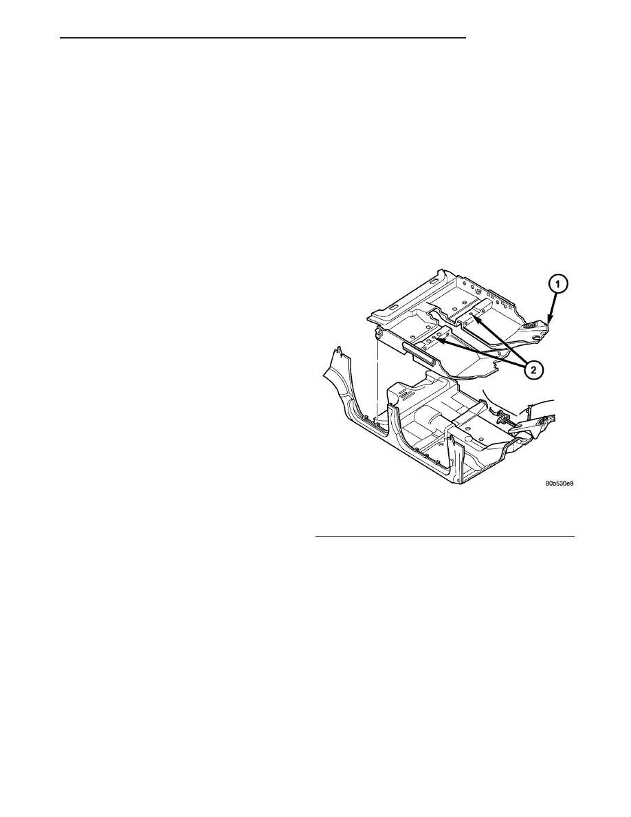
(10) Remove push pin fasteners (Fig. 3).
(11) Pull carpet from behind brake pedal, accelera-

tor pedal, and HVAC.

(12) Fold carpet to center of vehicle.
(13) Remove carpet from vehicle through passen-

ger door opening.

REMOVAL - JR-27 ONLY

(1) Lower convertible top to full down position.
(2) Remove front seats.
(3) Remove rear seat cushion.
(4) Remove floor console and center instrument

panel console.

(5) Remove door sill trim panels.
(6) Remove cowl trim panels.
(7) Remove quarter trim panels.
(8) Remove amplifier on passenger side of floor

pan, if so equipped.

(9) Remove wiring troughs holding carpet at out-

board ends of rear seat crossmember.

(10) Remove accelerator pedal.
(11) Remove instrument panel hush panels.
(12) Remove push-in fasteners from rear of carpet

attaching carpet to rear seat crossmember (Fig. 4).

Fig. 3 FLOOR CARPET

1 - FLOOR CARPET
2 - PUSH-PIN FASTENERS

JR

INTERIOR

23 - 85

A-PILLAR TRIM (Continued)

(13) Remove plastic sill retainers from metal clips

along door sill panel.

(14) Remove carpet from vehicle.

INSTALLATION

INSTALLATION

(1) Install carpet into vehicle through passenger

door opening.

(2) Unfold carpet into position.
(3) Install carpet behind brake pedal, accelerator

pedal, and HVAC.

(4) Install the tunnel push pin fastener.
(5) Install the front seat and crossmember push

pin fasteners.

(6) Install the two push pin fasteners into the floor

pan.

(7) Install

forward

instrument

panel

console.

(Refer

to

23

-

BODY/INTERIOR/FORWARD

INSTRUMENT PANEL CONSOLE - INSTALLA-
TION)

(8) Install floor console. (Refer to 23 - BODY/IN-

TERIOR/FLOOR CONSOLE - INSTALLATION)

(9) Install cowl trim panels. (Refer to 23 - BODY/

INTERIOR/COWL TRIM - INSTALLATION)

(10) Install lower B-pillar trim panels as neces-

sary. (Refer to 23 - BODY/INTERIOR/B-PILLAR
LOWER TRIM - INSTALLATION)

(11) Install bolts attaching front seat belts to floor.
(12) Install amplifier on passenger side of floor

pan, if equipped.

(13) Install front seats. (Refer to 23 - BODY/

SEATS/SEAT - REMOVAL)

(14) Install rear seat cushion. (Refer to 23 - BODY/

SEATS/SEAT CUSHION - INSTALLATION)

(15) Install the eight push pin fasteners into the

door opening sills.

(16) Install door opening sill plates.

INSTALLATION - JR-27 ONLY

(1) Position carpet in vehicle (Fig. 4).
(2) Install push in fasteners from rear of carpet

attaching carpet to rear seat crossmember.

(3) Install front seat push pin fasteners.
(4) Feed wiring connectors for the seats and ampli-

fier, if equipped, through slits in carpet.

(5) Install plastic sill retainers in metal clips along

door sill panel.

(6) Install wiring troughs attaching carpet at out-

board ends of rear seat crossmember.

(7) Install amplifier on passenger side of floor pan,

if so equipped.

(8) Install quarter trim panels.
(9) Install cowl trim panels.
(10) Install door sill trim panels.
(11) Install instrument panel hush panel.
(12) Install accelerator pedal.
(13) Install floor console and center instrument

panel console.

(14) Install rear seat cushion.
(15) Install front seats.
(16) Raise and secure convertible top.

Fig. 4 FLOOR CARPET JR-27

1 - DOOR SILL
2 - SEAT WIRING SLIT
3 - CARPET
4 - PUSH-PIN FASTENERS
5 - DOOR SILL
6 - AMPLIFIER WIRING SLIT
7 - REAR SEAT CROSSMEMBER

23 - 86

INTERIOR

JR

CARPETS AND FLOOR MATS (Continued)

CENTER HEADER TRIM PANEL

REMOVAL

REMOVE

(1) Remove both sun visor support centers (Refer

to 23 - BODY/INTERIOR/SUN VISOR - REMOVAL).

(2) Pull trim rearward to disengage clips attaching

header trim panel to header panel (Fig. 5).

(3) Remove header trim panel from vehicle.

INSTALLATION

(1) Position header trim panel on vehicle.
(2) Align the two locating pins on back of header

trim panel to holes in header panel.

(3) Engage the two clips on header trim panel to

slots in header panel.

(4) Attach the two sun visor support centers (Refer

to 23 - BODY/INTERIOR/SUN VISOR - INSTALLA-
TION).

COWL TRIM PANEL

REMOVAL

(1) Remove door sill trim panel.
(2) Remove screws attaching cowl trim panel to

inner cowl panel.

(3) Remove cowl trim panel from vehicle (Fig. 6).

INSTALLATION

(1) Position cowl trim panel to vehicle.
(2) Install screws attaching cowl trim panel to

inner cowl panel.

(3) Install door sill trim panel.

DOOR SILL TRIM PANEL

REMOVAL

(1) Using a fork type prying tool, disengage clips

holding door sill trim panel to door sill (Fig. 7).

(2) Starting at one end of sill trim panel, pull

upward on sill trim panel in order to disengage clips
attaching sill trim panel to door opening flange.

(3) Remove door sill trim panel from vehicle.

INSTALLATION

(1) Position door sill trim panel on vehicle.
(2) Align locating rib to net against cowl trim

panel.

(3) Engage clips on sill trim panel to door opening

flange.

Fig. 5 Center Header Trim Panel

1 - CENTER HEADER TRIM PANEL
2 - SUN VISOR SUPPORT CENTER

Fig. 6 Cowl Trim Panel

1 - LEFT COWL TRIM PANEL
2 - RIGHT COWL TRIM PANEL

Fig. 7 Door Sill Trim Panel

1 - LOCATING TAB
2 - DOOR SILL TRIM PANEL
3 - DOOR OPENING FLANGE
4 - DOOR SILL

JR

INTERIOR

23 - 87

NOTE: Check that header/A-pillar and quarter panel
weatherstrips are properly positioned. Incorrect posi-
tioning will interfere with clip engagement to door
opening flange and damage door sill trim panel.

(4) Engage clips attaching sill trim panel to door sill.

FLOOR CONSOLE

REMOVAL

(1) Raise parking brake lever as high as possible.
(2) Move transmission shifter to neutral position.
(3) Loosen set screw on front of shifter knob and

remove shift lever knob.

NOTE: Do not use a trim stick or tool to remove
transmission range indicator.

(4) Remove transmission range indicator bezel by

squeezing the sides slightly and lifting up until the
locking tabs are free of the floor console. Refer to
(Fig. 8) for pressure points.

(5) Disconnect transmission range indicator bezel

wire connector on the underside of bezel.

(6) Remove screws, next to floor shifter and in con-

sole storage compartment, attaching floor console to
brackets on floor pan (Fig. 9).

(7) Disconnect wire connector for floor console

accessories at floor pan.

(8) Remove console from vehicle.

NOTE: The grip portion of the parking brake lever
will only fit through the wider lower portion of the
slot in the floor console.

Fig. 8 Transmission Range Indicator Bezel

1 - BEZEL BOOT
2 - PRNDL BEZEL
3 - SHIFTER MECHANISM
4 - LOCATOR PIN
5 - WIRING CONNECTOR

Fig. 9 FLOOR CONSOLE

1 - SCREWS
2 - FLOOR CONSOLE
3 - CLIPS
4 - PARK BRAKE LEVER

23 - 88

INTERIOR

JR

DOOR SILL TRIM PANEL (Continued)


Content   ..  670  671  672  673   ..