Chrysler Sebring, Stratus sedan, Sebring Convertible. Manual - part 649


  Index      Chrysler     Chrysler Sebring, Stratus sedan, Sebring Convertible - service repair manual 2001-2007 year


Search            


Content   ..  647  648  649  650   ..


Chrysler Sebring, Stratus sedan, Sebring Convertible. Manual - part 649


methods may be used, but may not have all the ben-
efits of the recommended method.

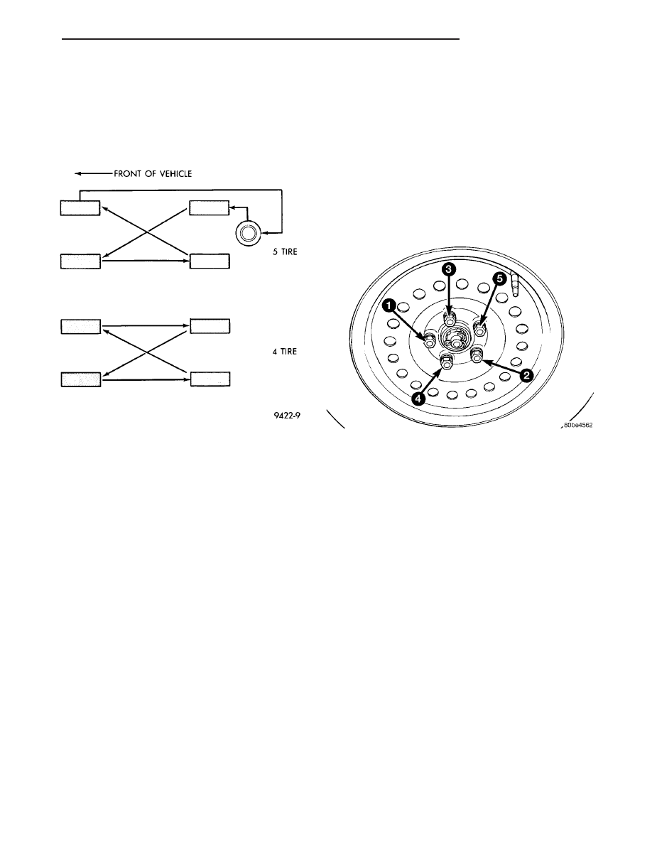
NOTE: Only the 4 tire rotation method may be used
if the vehicle is equipped with a low mileage or tem-
porary spare tire.

DIRECTIONAL TREAD PATTERN TIRES

Some vehicles are fitted with special high-perfor-

mance tires having a directional tread pattern. These
tires are designed to improve traction on wet pave-
ment. To obtain the full benefits of this design, the
tires must be installed so that they rotate in the cor-
rect direction. This is indicated by arrows on the tire
sidewalls.

When wheels and tires are being installed, extra

care is needed to ensure that this direction of rota-
tion is maintained.

Refer to Owner’s Manual for rotation schedule.

REMOVAL - TIRE AND WHEEL ASSEMBLY

(1) Raise the vehicle so the tires clear ground

level. (Refer to LUBRICATION & MAINTENANCE/
HOISTING - STANDARD PROCEDURE)

(2) If the vehicle is equipped with wheel covers,

remove the cover from the wheel by prying it off with
an appropriate wheel cover removal tool.

(3) Remove the wheel mounting (lug) nuts from

the studs.

(4) Remove the tire and wheel assembly from the

hub.

INSTALLATION - TIRE AND WHEEL ASSEMBLY

(1) To install the tire and wheel assembly, first

position it properly on the studs and hub mounting
surface using the hub pilot as a guide.

CAUTION: Never apply oil or grease to the wheel
mounting studs or nuts.

(2) Install and progressively tighten the five wheel

mounting (lug) nuts in the proper sequence (Fig. 12)
until half the specified torque is reached. Repeat the
sequence, tightening the wheel mounting (lug) nuts
to a final torque of 135 N·m (100 ft. lbs.).

(3) If equipped with wheel covers, align the valve

stem notch in the wheel cover with the valve stem on
the wheel. By hand, tap the wheel cover onto the
wheel until it is fully seated against the wheel.

(4) Lower the vehicle.

TIRES

DESCRIPTION

DESCRIPTION - TIRE

Tires are designed and engineered for each specific

vehicle. They provide the best overall performance
for normal operation. The ride and handling charac-
teristics match the vehicle’s requirements. With
proper care they will give excellent reliability, trac-
tion, skid resistance, and tread life.

Driving habits have more effect on tire life than

any other factor. Careful drivers will obtain, in most
cases, much greater mileage than severe use or care-
less drivers. A few of the driving habits which will
shorten the life of any tire are:

• Rapid acceleration

• Severe application of brakes

• High-speed driving

Fig. 11 Forward-Cross Tire Rotation Method

Fig. 12 Wheel Nut Tightening Sequence

JR

TIRES/WHEELS

22 - 7

TIRES/WHEELS (Continued)

• Taking turns at excessive speeds

• Striking curbs and other obstacles

• Operating vehicle with over or under inflated

tire pressures

Radial ply tires are more prone to irregular tread

wear. It is important to follow the tire rotation inter-
val shown in the section on Tire Rotation. This will
help to achieve a greater tread-life potential.

TIRE IDENTIFICATION

Tire type, size, load index and speed rating are

encoded in the letters and numbers imprinted on the
side wall of the tire. Refer to the Tire Identification
chart to decipher the code. For example purposes, the
tire size P225/60 R 16 97 T is used in the chart. An
All Season type tire will also have either M + S, M &
S or M - S (indicating mud and snow traction)
imprinted on the side wall. An Extra or Light Load
marking “XL” or “LL” may also be listed on the side-
wall. The absence of an “XL” or “LL” marking infers
a standard load tire.

TIRE IDENTIFICATION

P

TIRE TYPE (Not

present on all tires)

P - Passenger

T - Temporary

C - Commercial

LT - Light Truck

225

SECTIONAL WIDTH

SHOWN IN
MILLIMETERS

60

ASPECT RATIO

SECTIONAL HEIGHT
÷ SECTIONAL WIDTH
(Refer to Aspect Ratio
Figure 13 )

R

CONSTRUCTION

TYPE

R - RADIAL

B - BIAS BELTED

D - DIAGONAL (BIAS)

16

WHEEL DIAMETER

SHOWN IN INCHES

97

LOAD INDEX

*

T

SPEED RATING

*

* NOTE: Consult the tire manufacturer regarding
any questions on tire specifications or capabilities.

TIRE CHAINS

Refer to the owners manual supplied with the vehi-

cle to determine whether the use of tire chains is per-
mitted on this vehicle.

DESCRIPTION - RADIAL-PLY TIRES

Radial-ply tires improve handling, tread life and

ride quality, and decrease rolling resistance.

Radial-ply tires must always be used in sets of

four. Under no circumstances should they be used on
the front only. They may be mixed with temporary
spare tires when necessary. A maximum speed of 80
km/h (50 mph) is recommended while a temporary
spare is in use.

Radial-ply tires have the same load-carrying capac-

ity as other types of tires of the same size. They also
use the same recommended inflation pressures.

The use of oversized tires, either in the front or

rear of the vehicle, can cause vehicle drive train fail-
ure. This could also cause inaccurate wheel speed
signals when the vehicle is equipped with Antilock
Brakes.

The use of tires from different manufactures on the

same vehicle is NOT recommended. The proper tire
pressure should be maintained on all four tires.

DESCRIPTION - REPLACEMENT TIRES

WARNING: FAILURE TO EQUIP THE VEHICLE WITH
TIRES HAVING ADEQUATE SPEED CAPABILITY
CAN RESULT IN SUDDEN TIRE FAILURE.

Fig. 13 Tire Aspect Ratio

1 - SECTIONAL WIDTH
2 - SECTIONAL HEIGHT

22 - 8

TIRES/WHEELS

JR

TIRES (Continued)

WARNING: IN ORDER TO MAINTAIN THE SPEED
CAPABILITY OF THE VEHICLE, REPLACEMENT
TIRES MUST HAVE SPEED RATINGS EQUAL TO OR
HIGHER THAN THOSE FITTED TO THE VEHICLE AS
ORIGINAL EQUIPMENT. IF TIRES WITH LOWER
SPEED RATINGS ARE FITTED, THE VEHICLE’S
HANDLING MAY BE AFFECTED AND THE SPEED
CAPABILITY OF THE VEHICLE MAY BE LOWERED
TO THE MAXIMUM SPEED CAPABILITY OF THE
REPLACEMENT TIRES. TO AVOID AN ACCIDENT
RESULTING IN SEVERE OR FATAL INJURY, CON-
SULT THE TIRE MANUFACTURER IN REGARDS TO
MAXIMUM SPEED RATINGS.

It is recommended that tires equivalent to the orig-

inal equipment tires be used when replacement is
needed.

Failure to use equivalent replacement tires may

adversely affect the safety and handling of the vehi-
cle.

The original equipment tires provide a proper com-

bination of many characteristics such as:

• Ride

• Noise

• Handling

• Durability

• Tread life

• Traction

• Rolling resistance

• Speed capability
The use of tires smaller than the minimum tire

size approved for the vehicle can result in tire over-
loading and failure.

Use tires that have the approved load rating for

the vehicle and never overload them. Failure to equip
the vehicle with tires having adequate speed capabil-
ity can result in sudden tire failure and loss of vehi-
cle control.

The use of oversize tires may cause interference

with vehicle components. Under extremes of suspen-
sion and steering travel, interference with vehicle
components may cause tire damage.

DESCRIPTION - SPARE TIRE (TEMPORARY)

The compact temporary spare tire is designed for

emergency use only. The original tire should be
repaired or replaced at the first opportunity, then
reinstalled. Do not exceed speeds of 80 km/h (50
mph) when using the temporary spare tire. Refer to
Owner’s Manual for complete details.

DIAGNOSIS AND TESTING

DIAGNOSIS AND TESTING - TIRE NOISE

Unusual tire noise can be associated with tire and

wheel vibration or irregular tire wear. For vibration,
(Refer to 22 - TIRES/WHEELS - DIAGNOSIS AND
TESTING). For irregular tire wear, (Refer to 22 -
TIRES/WHEELS/TIRES - DIAGNOSIS AND TEST-
ING).

DIAGNOSIS AND TESTING - TIRE/VEHICLE
LEAD

(Refer to 2 - SUSPENSION/WHEEL ALIGNMENT

- DIAGNOSIS AND TESTING)

DIAGNOSIS AND TESTING - TIRE WEAR
PATTERNS

Under inflation will cause wear on the shoulders of

tire. Over inflation will cause wear at the center of
tire.

Excessive camber causes the tire to run at an

angle to the road. One side of tread is then worn
more than the other (Fig. 14).

Excessive toe-in or toe-out causes wear on the

tread edges and a feathered effect across the tread
(Fig. 14).

DIAGNOSIS AND TESTING - TREAD WEAR
INDICATORS

Tread wear indicators are molded into the bottom

of the tread grooves. When tread depth is 1.6 mm
(1/16 in.), the tread wear indicators will appear as a
13 mm (1/2 in.) band (Fig. 15).

Tire replacement is necessary when indicators

appear in two or more grooves or if localized balding
occurs.

STANDARD PROCEDURE

STANDARD PROCEDURE - TIRE INFLATION
PRESSURES

The specified tire pressures have been chosen to

provide safe operation, vehicle stability, and a smooth
ride. The proper tire pressure specification can be
found on the Tire Inflation Pressure Label provided
with the vehicle (usually on the driver’s side B-pil-
lar).

A quality air pressure gauge is recommended to

check tire air pressure. Tire pressure should be
checked cold once per month. Check tire pressure
more frequently when the weather temperature var-
ies widely. Tire pressure will decrease when the out-
door temperature drops. After checking the air
pressure, replace valve cap finger tight.

JR

TIRES/WHEELS

22 - 9

TIRES (Continued)

Inflation pressures specified on the Tire Inflation

Pressure Label are always the cold inflation pressure
of the tire. Cold inflation pressure is obtained after
the vehicle has not been operated for at least 3
hours, or the vehicle is driven less than one mile
after being inoperative for 3 hours. Tire inflation
pressures may increase from 2 to 6 pounds per
square inch (psi) during operation. Do not reduce this
normal pressure buildup.

Improper inflation can cause:
• Uneven wear patterns

• Reduced tread life

• Reduced fuel economy

• Unsatisfactory ride

• The vehicle to drift.

WARNING: OVER OR UNDER INFLATED TIRES CAN
AFFECT VEHICLE HANDLING. THE TIRE CAN FAIL
SUDDENLY, RESULTING IN LOSS OF VEHICLE
CONTROL.

Under inflation causes rapid shoulder wear, tire

flexing, and can result in tire failure (Fig. 16).

Over inflation causes rapid center wear and loss of

the tire’s ability to cushion shocks (Fig. 17).

Fig. 14 Tire Wear Patterns

Fig. 15 Tread Wear Indicators

1 - TREAD ACCEPTABLE
2 - TREAD UNACCEPTABLE
3 - WEAR INDICATOR

Fig. 16 Under Inflation Wear

1 - THIN TIRE TREAD AREAS

22 - 10

TIRES/WHEELS

JR

TIRES (Continued)


Content   ..  647  648  649  650   ..