Chrysler Sebring, Stratus sedan, Sebring Convertible. Manual - part 647


  Index      Chrysler     Chrysler Sebring, Stratus sedan, Sebring Convertible - service repair manual 2001-2007 year


Search            


Content   ..  645  646  647  648   ..


Chrysler Sebring, Stratus sedan, Sebring Convertible. Manual - part 647


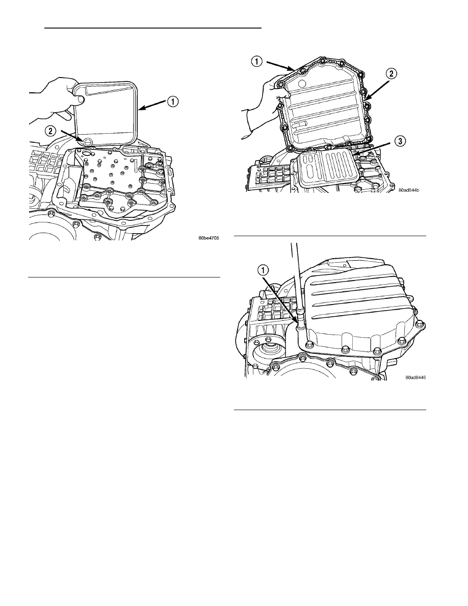
(3) Install transaxle oil filter (Fig. 376). Inspect

the o-ring and replace if necessary.

(4) Ensure the transaxle oil pan and transaxle

case sealing surfaces are clean and dry. Install an
1/8” bead of Mopar

t ATF RTV (MS-GF41) to the oil

pan and install (Fig. 377). Torque oil pan-to-transaxle
case bolts (Fig. 378) to 19 N·m (165 in. lbs.).

(5) Lower vehicle.
(6) Connect transmission range sensor connector.
(7) Install manual valve lever to manual shaft.
(8) Install gearshift cable to manual valve lever.
(9) Connect battery negative cable.
(10) Fill transaxle with Mopar

t ATF +4 Transmis-

sion fluid. (Refer to 21 - TRANSMISSION/TRANS-
AXLE/AUTOMATIC - 41TE/FLUID - STANDARD
PROCEDURE)

Fig. 376 Install Oil Filter and O-Ring

1 - OIL FILTER
2 - O-RING

Fig. 377 Oil Pan

1 - OIL PAN
2 - 1/8 INCH BEAD OF MOPAR ATF RTV (MS-GF41)
3 - OIL FILTER

Fig. 378 Oil Pan Bolts

1 - OIL PAN BOLTS (USE RTV UNDER BOLT HEADS)

JR

41TE AUTOMATIC TRANSAXLE

21 - 349

VALVE BODY (Continued)

TIRES/WHEELS

TABLE OF CONTENTS

page

page

TIRES/WHEELS

DIAGNOSIS AND TESTING - TIRE AND

WHEEL VIBRATION

. . . . . . . . . . . . . . . . . . . . . 1

STANDARD PROCEDURE

STANDARD PROCEDURE - TIRE AND

WHEEL BALANCE . . . . . . . . . . . . . . . . . . . . . . 5

STANDARD PROCEDURE - TIRE AND

WHEEL MATCH MOUNTING . . . . . . . . . . . . . . 6

STANDARD PROCEDURE - TIRE AND

WHEEL ROTATION . . . . . . . . . . . . . . . . . . . . . 6

REMOVAL - TIRE AND WHEEL ASSEMBLY

. . . . 7

INSTALLATION - TIRE AND WHEEL

ASSEMBLY

. . . . . . . . . . . . . . . . . . . . . . . . . . . 7

TIRES

DESCRIPTION

DESCRIPTION - TIRE

. . . . . . . . . . . . . . . . . . . 7

DESCRIPTION - RADIAL-PLY TIRES

. . . . . . . . 8

DESCRIPTION - REPLACEMENT TIRES

. . . . . 8

DESCRIPTION - SPARE TIRE

(TEMPORARY) . . . . . . . . . . . . . . . . . . . . . . . . 9

DIAGNOSIS AND TESTING

DIAGNOSIS AND TESTING - TIRE NOISE

. . . . 9

DIAGNOSIS AND TESTING - TIRE/VEHICLE

LEAD . . . . . . . . . . . . . . . . . . . . . . . . . . . . . . . . 9

DIAGNOSIS AND TESTING - TIRE WEAR

PATTERNS . . . . . . . . . . . . . . . . . . . . . . . . . . . 9

DIAGNOSIS AND TESTING - TREAD WEAR

INDICATORS . . . . . . . . . . . . . . . . . . . . . . . . . . 9

STANDARD PROCEDURE

STANDARD PROCEDURE - TIRE INFLATION

PRESSURES . . . . . . . . . . . . . . . . . . . . . . . . . . 9

STANDARD PROCEDURE - TIRE

PRESSURE FOR HIGH SPEED
OPERATION . . . . . . . . . . . . . . . . . . . . . . . . . 11

STANDARD PROCEDURE - TIRE LEAK

REPAIRING . . . . . . . . . . . . . . . . . . . . . . . . . . 11

CLEANING - TIRES

. . . . . . . . . . . . . . . . . . . . . . 11

WHEELS

DESCRIPTION

. . . . . . . . . . . . . . . . . . . . . . . . . 11

DIAGNOSIS AND TESTING - WHEEL

INSPECTION

. . . . . . . . . . . . . . . . . . . . . . . . . 12

CLEANING - ALUMINUM WHEEL CARE

. . . . . . 12

SPECIFICATIONS

WHEEL

. . . . . . . . . . . . . . . . . . . . . . . . . . . . . 12

WHEEL MOUNTING STUDS - FRONT

REMOVAL

. . . . . . . . . . . . . . . . . . . . . . . . . . . . . 13

INSTALLATION

. . . . . . . . . . . . . . . . . . . . . . . . . 13

WHEEL MOUNTING STUDS - REAR

REMOVAL

. . . . . . . . . . . . . . . . . . . . . . . . . . . . . 14

INSTALLATION

. . . . . . . . . . . . . . . . . . . . . . . . . 14

TIRES/WHEELS

DIAGNOSIS AND TESTING - TIRE AND WHEEL
VIBRATION

Tire and wheel imbalance, runout and force varia-

tion can cause vehicles to exhibit steering wheel
vibration.

VISUAL INSPECTION

Visual inspection of the vehicle is recommended

prior to road testing or performing any other proce-
dure. Raise vehicle on a suitable hoist. (Refer to
LUBRICATION

&

MAINTENANCE/HOISTING

-

STANDARD PROCEDURE)

Inspect for the following:
• Verify correct (OEM) wheel and tire, as well as

correct wheel weights. Aluminum wheels require
unique wheel weights. They are designed to fit the
contour of the wheel (Fig. 1).

• Inspect tires and wheels for damage, mud pack-

ing and unusual wear; correct as necessary.

• Check and adjust tire air pressure to the pres-

sure listed on the label attached to the rear face of
the driver’s door.

ROAD TEST

Road test vehicle on a smooth road for a least five

miles to warm tires (remove any flat spots). Lightly
place hands on steering wheel at the 10:00 and 2:00
positions while slowly sweeping up and down from 90
to 110 km/h (55 to 70 mph) where legal speed limits
allow.

Observe the steering wheel for:
• Visual Nibble (oscillation: clockwise/counter-

clockwise, usually due to tire imbalance)

• Visual Buzziness (high frequency, rapid vibra-

tion up and down)

To rule out vibrations due to brakes or powertrain:
• Lightly apply brakes at speed; if vibration occurs

or is enhanced, vibration is likely due to causes other
than tire and wheel assemblies.

• Shift transmission into neutral while vibration

is occurring; if vibration is eliminated, vibration is

JR

TIRES/WHEELS

22 - 1

likely due to causes other than tire and wheel assem-
blies.

For brake vibrations, (Refer to 5 - BRAKES -

BASE/HYDRAULIC/MECHANICAL/ROTORS

-

DIAGNOSIS AND TESTING).

For powertrain vibrations, (Refer to 3 - DIFFER-

ENTIAL & DRIVELINE - DIAGNOSIS AND TEST-
ING).

For tire and wheel assembly vibrations, continue

with this diagnosis and testing procedure.

TIRE AND WHEEL BALANCE

(1) Balance the tire and wheel assemblies as nec-

essary following the wheel balancer manufacturer’s
instructions and using the information listed in Stan-
dard Procedure - Tire And Wheel Balance. (Refer to
22 - TIRES/WHEELS - STANDARD PROCEDURE)

(2) Road test the vehicle for at least 5 miles, fol-

lowing the format described in Road Test.

(3) If the vibration persists, continue with this

diagnosis and testing procedure.

TIRE AND WHEEL RUNOUT/MATCH MOUNTING

(1) System Radial Runout. This on-the-vehicle

system check will measure the radial runout includ-
ing the hub, wheel and tire.

(a) Raise vehicle so tires clear floor. (Refer to

LUBRICATION & MAINTENANCE/HOISTING -
STANDARD PROCEDURE)

(b) Apply masking tape around the circumfer-

ence of the tire in the locations to be measured
(Fig. 2). Do not overlap the tape.

(c) Check system runout using Dial Indicator

Set, Special Tool C-3339A with 25-W wheel, or
equivalent. Place the end of the indicator against
each taped area (one at a time) (Fig. 2) and rotate

the tire and wheel. System radial runout should
not exceed 0.76 mm (0.030 inch) with no tread
“dips” or “steps.” Tread “dips” and “steps” can be
identified by spikes of the dial indicator gauge.
• Tread 9dips9; Rapid decrease then increase in

dial indicator reading over 101.6 mm (4.0 inch) of
tread circumference.

• Tread 9steps9; Rapid decrease or increase in dial

indicator reading over 101.6 mm (4.0 inch) of tread
circumference.

(d) If system runout is excessive, re-index the

tire and wheel assembly on the hub. Remove
assembly from vehicle and install it back on the
hub two studs over from original mounting posi-
tion. If re-indexing the tire and wheel assembly
corrects or reduces system runout, check hub
runout and repair as necessary (Refer to 5 -
BRAKES

-

BASE/HYDRAULIC/MECHANICAL/

ROTORS - DIAGNOSIS AND TESTING).

(e) If system runout is still excessive, continue

with this diagnosis and testing procedure.

(2) Tire and Wheel Assembly Radial Runout.

This radial runout check is performed with the tire
and wheel assembly off the vehicle.

(a) Remove tire and wheel assembly from vehicle

and install it on a suitable wheel balancer.

(b) Check system runout using Dial Indicator

Set, Special Tool C-3339A with 25-W wheel, or
equivalent. Place the end of the indicator against
each taped area (one at a time) (Fig. 2) and rotate
the tire and wheel. Radial runout should not
exceed 0.76 mm (0.030 inch) with no tread “dips”

Fig. 1 Aluminum Wheel Weight

1 - TIRE
2 - WHEEL
3 - WHEEL WEIGHT

Fig. 2 Radial Runout Measurement

1 - MASKING TAPE
2 - DIAL INDICATOR

22 - 2

TIRES/WHEELS

JR

TIRES/WHEELS (Continued)


Content   ..  645  646  647  648   ..