Chrysler Sebring, Stratus sedan, Sebring Convertible. Manual - part 646
 

  Index      Chrysler     Chrysler Sebring, Stratus sedan, Sebring Convertible - service repair manual 2001-2007 year


Search            


Content   ..  644  645  646  647   ..


Chrysler Sebring, Stratus sedan, Sebring Convertible. Manual - part 646


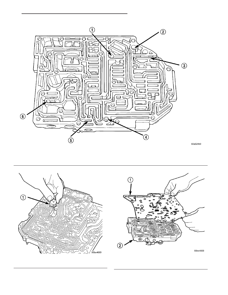
Fig. 361 Ball Check Location

1 - (#4) BALL CHECK LOCATION
2 - (#2) BALL CHECK LOCATION
3 - RETAINER

4 - (#3) BALL CHECK LOCATION
5 - LOW/REVERSE SWITCH VALVE
6 - T/C LIMIT VALVE

Fig. 362 Install Thermal Valve

1 - THERMAL VALVE

Fig. 363 Install Separator Plate

1 - SEPARATOR PLATE
2 - VALVE BODY

JR

41TE AUTOMATIC TRANSAXLE

21 - 345

VALVE BODY (Continued)

(8) Install the overdrive clutch (#5) check valve to

separator plate (Fig. 364)

(9) Install oil screen to separator plate (Fig. 365).

(10) Install transfer plate to valve body and sepa-

rator plate. Make sure oil screen and #5 check valve
do not bind (Fig. 366).

(11) Install twenty-four transfer plate to valve

body screws (Fig. 367) and torque to 5 N·m (45 in.
lbs.).

Fig. 364 Install Overdrive Clutch (#5) Check Valve

1 - OVERDRIVE CLUTCH (#5) CHECK VALVE

Fig. 365 Install Oil Screen

1 - OIL SCREEN

Fig. 366 Install Transfer Plate

1 - TRANSFER PLATE

Fig. 367 Install Valve Body to Transfer Plate Screws

1 - SCREW (24)
2 - TRANSFER PLATE
3 - VALVE BODY

21 - 346

41TE AUTOMATIC TRANSAXLE

JR

VALVE BODY (Continued)

(12) Install 2/4 Accumulator components as shown

in (Fig. 368).

(13) Torque 2/4 Accumulator retainer to 5 N·m (45

in. lbs.) (Fig. 369).

(14) Install

Manual

Shaft/Rooster

Comb

and

Transmission Range Sensor (Fig. 370).

(15) Make sure Manual Valve control pin is con-

tained within the rooster comb slot (Fig. 371). Install
Transmission Range Sensor retaining screw (Fig.
371) and torque to 5 N·m (45 in. lbs.).

(16) Install manual shaft seal (Fig. 372).

Fig. 368 2/4 Accumulator Assembly

1 - VALVE BODY
2 - RETAINER PLATE
3 - DETENT SPRING
4 - RETURN SPRINGS
5 - PISTON

Fig. 369 2/4 Accumulator Retaining Plate

1 - 2–4 ACCUMULATOR RETAINING PLATE
2 - DETENT SPRING

Fig. 370 Install Manual Shaft/Rooster Comb and

Transmission Range Sensor

1 - TRANSMISSION RANGE SENSOR
2 - MANUAL SHAFT
3 - ROOSTER COMB

Fig. 371 Install Transmission Range Sensor

Retaining Screw

1 - TRANSMISSION RANGE SENSOR
2 - MANUAL VALVE CONTROL PIN
3 - RETAINING SCREW

JR

41TE AUTOMATIC TRANSAXLE

21 - 347

VALVE BODY (Continued)

INSTALLATION

NOTE: If valve body assembly is being replaced or
reconditioned, it is necessary to perform the PCM
Quick Learn Procedure. (Refer to 8 - ELECTRICAL/
ELECTRONIC CONTROL MODULES/TRANSMISSION
CONTROL MODULE - STANDARD PROCEDURE)

(1) Install underdrive and overdrive accumulators

(Fig. 373).

(2) Install valve body assembly to transaxle (Fig.

374). Install and torque valve body-to-transaxle case
bolts (Fig. 375) to 12 N·m (105 in. lbs.).

Fig. 372 Manual Shaft Seal

1 - SEAL
2 - MANUAL SHAFT

Fig. 373 Underdrive and Overdrive Accumulators

1 - OVERDRIVE PISTON AND SPRING
2 - UNDERDRIVE PISTON AND SPRING

Fig. 374 Valve Body Removal/Installation

1 - VALVE BODY

Fig. 375 Valve Body-to-Case Bolts

1 - VALVE BODY ATTACHING BOLTS (18)
2 - VALVE BODY

21 - 348

41TE AUTOMATIC TRANSAXLE

JR

VALVE BODY (Continued)


Content   ..  644  645  646  647   ..