Chrysler Sebring, Stratus sedan, Sebring Convertible. Manual - part 645


  Index      Chrysler     Chrysler Sebring, Stratus sedan, Sebring Convertible - service repair manual 2001-2007 year


Search            


Content   ..  643  644  645  646   ..


Chrysler Sebring, Stratus sedan, Sebring Convertible. Manual - part 645


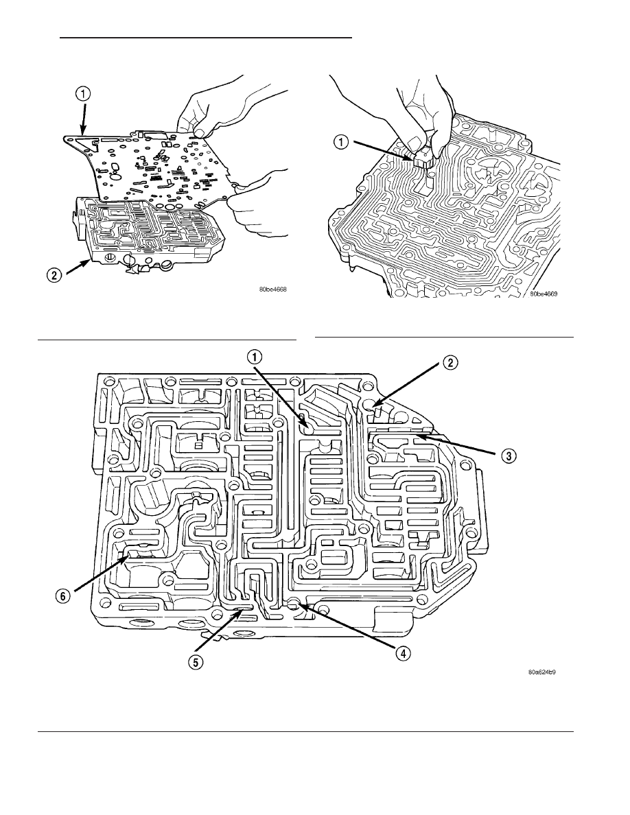
Fig. 351 Remove Separator Plate

1 - SEPARATOR PLATE
2 - VALVE BODY

Fig. 352 Remove Thermal Valve

1 - THERMAL VALVE

Fig. 353 Ball Check Location

1 - (#4) BALL CHECK LOCATION
2 - (#2) BALL CHECK LOCATION
3 - RETAINER

4 - (#3) BALL CHECK LOCATION
5 - LOW/REVERSE SWITCH VALVE
6 - T/C LIMIT VALVE

JR

41TE AUTOMATIC TRANSAXLE

21 - 341

VALVE BODY (Continued)

(13) Remove dual retainer plate using Tool 6301

(Fig. 354).

(14) Remove regulator valve spring retainer (Fig.

355).

(15) Remove remaining retainers as shown in (Fig.

356).

(16) Remove valves and springs as shown in (Fig.

357).

NOTE: Refer to Valve Body Cleaning and Inspection
for cleaning procedures.

ASSEMBLY

NOTE: If valve body assembly is reconditioned, the
PCM/TCM Quick Learn Procedure must be per-
formed. (Refer to 8 - ELECTRICAL/ELECTRONIC
CONTROL

MODULES/TRANSMISSION

CONTROL

MODULE - STANDARD PROCEDURE)

(1) Install valves and springs as shown in (Fig.

357).

(2) Install regulator valve spring retainer (Fig.

358).

(3) Install dual retainer plate using Tool 6301 (Fig.

359).

Fig. 354 Remove Dual Retainer Plate using Tool

6301

1 - TOOL 6301
2 - RETAINER

Fig. 355 Remove Regulator Valve Spring Retainer

using Tool 6302

1 - TOOL 6302
2 - RETAINER

Fig. 356 Valve Retainer Location

1 - RETAINER
2 - RETAINER

21 - 342

41TE AUTOMATIC TRANSAXLE

JR

VALVE BODY (Continued)

Fig. 357 Springs and Valves Location

1 - VALVE BODY

5 - MANUAL VALVE

2 - T/C REGULATOR VALVE

6 - CONVERTER CLUTCH SWITCH VALVE

3 - L/R SWITCH VALVE

7 - SOLENOID SWITCH VALVE

4 - CONVERTER CLUTCH CONTROL VALVE

8 - REGULATOR VALVE

Fig. 358 Install Regulator Valve Spring Retainer

using Tool 6302

1 - TOOL 6302
2 - RETAINER

Fig. 359 Install Dual Retainer Plate using Tool 6301

1 - TOOL 6301
2 - RETAINER

JR

41TE AUTOMATIC TRANSAXLE

21 - 343

VALVE BODY (Continued)

(4) Verify that all retainers are installed as shown

in (Fig. 360). Retainers should be flush or below
valve body surface.

(5) Install check balls into position as shown in

(Fig. 361). If necessary, secure them with petrolatum
or transmission assembly gel for assembly ease.

(6) Install thermal valve into transfer plate (Fig.

362).

(7) Install separator plate to valve body (Fig. 363).

Fig. 360 Valve Retainer Location

1 - RETAINER
2 - RETAINER

21 - 344

41TE AUTOMATIC TRANSAXLE

JR

VALVE BODY (Continued)


Content   ..  643  644  645  646   ..