Chrysler Sebring, Stratus sedan, Sebring Convertible. Manual - part 556


  Index      Chrysler     Chrysler Sebring, Stratus sedan, Sebring Convertible - service repair manual 2001-2007 year


Search            


Content   ..  554  555  556  557   ..


Chrysler Sebring, Stratus sedan, Sebring Convertible. Manual - part 556


(16) Remove brake tube routing bracket from left

lower control arm rear mounting bolt.

(17) Disconnect fuel tube bundle routing support

above crossmember.

(18) Position transmission jack under center of

front suspension crossmember to support it.

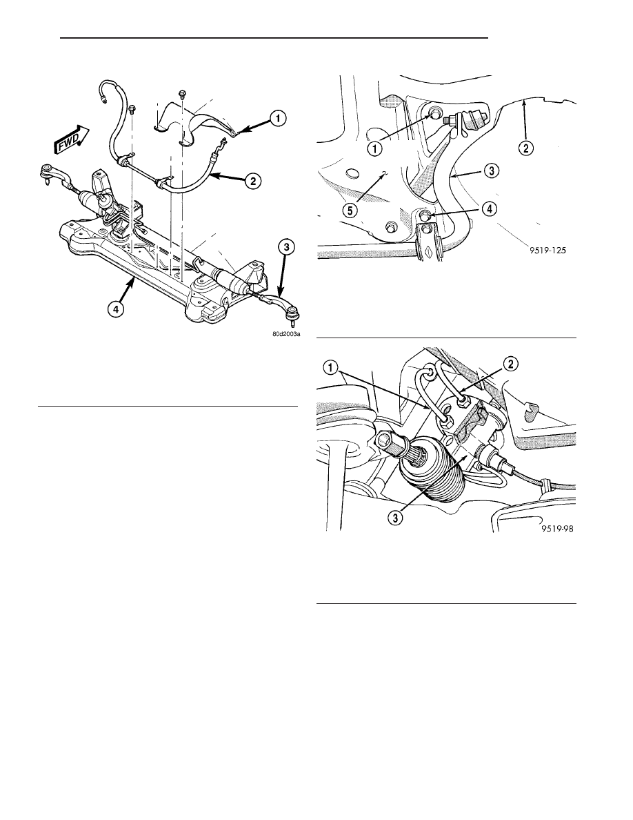
(19) On each side of the vehicle, remove the 2 bolts

attaching the front and rear of the front suspension
crossmember to the frame rails of vehicle (Fig. 9).

(20) Using transmission jack, lower front suspen-

sion crossmember enough to allow steering gear to be
removed from crossmember. When lowering front
suspension crossmember, do not let crossmem-
ber hang from lower control arms, weight of
crossmember must be supported by transmis-
sion jack.

(21) Remove power steering pressure and return

hoses from the power steering gear fluid ports (Fig.
10).

(22) Remove wiring harness connector from power

steering fluid pressure switch.

(23) Remove 4 bolts fastening power steering gear

to front suspension crossmember.

(24) Remove power steering gear from front sus-

pension crossmember.

(25) Transfer required parts from removed gear to

replacement gear if a new gear is being installed.

DISASSEMBLY

(1) Using a screwdriver, pry the sleeve out of the

mounting bolt isolator (Fig. 11).

(2) Pry the mounting bolt isolator bushing from

the steering gear mounting bracket.

ASSEMBLY

(1) Lubricate replacement mounting bolt isolator

bushing using Mopar, Silicone Spray Lube or an
equivalent.

(2) Install the mounting bolt isolator bushing into

the steering gear mounting bracket from the bottom
side of the bracket (Fig. 12).

Fig. 8 Pressure Hose Mounting To Crossmember

1 - HEAT SHIELD (TYPICAL)
2 - PRESSURE HOSE
3 - POWER STEERING GEAR
4 - FRONT SUSPENSION CROSSMEMBER

Fig. 9 Crossmember To Body Attaching Bolts

1 - CROSSMEMBER FRONT MOUNTING BOLT
2 - LOWER CONTROL ARM
3 - STABILIZER BAR
4 - CROSSMEMBER REAR MOUNTING BOLT
5 - FRONT SUSPENSION CROSSMEMBER

Fig. 10 Power Steering Pressure And Return Hose

At Steering Gear

1 - POWER STEERING PRESSURE HOSE
2 - POWER STEERING RETURN HOSE
3 - POWER STEERING GEAR

JR

GEAR

19 - 23

GEAR (Continued)

(3) Install mounting bolt isolator bushing sleeve

into isolator bushing by pressing the sleeve into the
bushing by hand (Fig. 13).

INSTALLATION

(1) Install power steering gear on front suspension

crossmember. Install all four steering gear mounting
bolts. Tighten bolts to a torque of 68 N·m (50 ft. lbs.).

(2) Install

power

steering

fluid

pressure

and

return hoses to ports of power steering gear (Fig. 10).
Tighten power steering fluid pressure and return
hose tube nuts to a torque of 31 N·m (275 in. lbs.).

(3) Using transmission jack, raise front suspension

crossmember and steering gear against body of vehi-
cle.

CAUTION: When front suspension crossmember is
installed back in vehicle, crossmember MUST be
aligned with positioning marks previously scribed
into body of vehicle. This MUST be done to main-
tain NET BUILD front suspension alignment set-
tings.

(4) Start two rear mounting bolts into body tap-

ping plates attaching front suspension crossmember
to body of vehicle. Then install two front bolts attach-
ing front suspension crossmember to frame rails of
vehicle. Tighten all four mounting bolts evenly until
front suspension crossmember is against body of
vehicle at all four mounting points. Tighten bolts to
approximately 2 N·m (20 in. lbs.) torque to hold front
suspension crossmember in position. Do not over-
tighten.

(5) Using a soft face hammer, tap front suspension

crossmember into position until it is aligned with
previously scribed positioning marks on body of vehi-
cle.

(6) Once front suspension crossmember is correctly

positioned, tighten two rear crossmember mounting
bolts to 163 N·m (120 ft. lbs.) torque. Then tighten
two front crossmember to frame rail attaching bolts
to 163 N·m (120 ft. lbs.) torque.

(7) Lower transmission jack.
(8) Connect fuel tube bundle routing support above

crossmember.

(9) Install brake tube routing bracket onto left

lower control arm rear mounting bolt threads.

(10) Install screws fastening power steering pres-

sure hose routing clamps to crossmember (Fig. 8).
Tighten screws to 45 N·m (33 ft. lbs.) torque.

(11) Position steering gear heat shield on cross-

member and install fasteners (Fig. 8).

Fig. 11 Mounting Bolt Isolator Sleeve Removal

1 - SCREWDRIVER
2 - ISOLATOR BUSHING SLEEVE
3 - STEERING GEAR MOUNTING BRACKET

Fig. 12 Installing Mounting Bolt

1 - STEERING GEAR MOUNTING BOLT ISOLATOR BUSHING
2 - STEERING GEAR MOUNTING BRACKET
3 - STEERING GEAR

Fig. 13 Mounting Bolt Isolator Sleeve Installation

1 - STEERING GEAR MOUNTING BRACKET
2 - ISOLATOR BUSHING SLEEVE
3 - STEERING GEAR MOUNTING BOLT ISOLATOR BUSHING

19 - 24

GEAR

JR

GEAR (Continued)

(12) Install 3 bolts attaching rear engine mount to

crossmember (Fig. 7). If equipped, make sure
manual transmission bracket is positioned in
place before installing bolts (Fig. 7). 
Tighten
bolts to 65 N·m (48 ft. lbs.) torque.

(13) Loosely install two shock absorber clevis-to-

lower control arm thru-bolts and nuts (Fig. 6). Do not
tighten bolts at this time.

(14) Install tie rod seal boot heat shield on tie rod

end (Fig. 14).

(15) Install tie rod end into steering knuckle. Start

tie rod end-to-steering knuckle attaching nut onto tie
rod stud. While holding stud stationary, tighten nut.
To properly torque nut, use a crowfoot and socket as
shown and tighten nut to 55 N·m (40 ft. lbs.) torque
(Fig. 14).

(16) Install and tighten two stabilizer bar bushing

clamp-to-body attaching bolts to 61 N·m (45 ft. lbs.)
torque.

(17) Install fasteners attaching drive-belt splash

shield to crossmember.

CAUTION: When supporting lower control arm with
jack stand, do not position jack stand under the ball
joint cap on the lower control arm. Position in area
of lower control arm shown in (Fig. 15).

(18) Lower vehicle and support front end of vehicle

by positioning jack stands as shown at each lower
control arm as vehicle is lowered (Fig. 15). Continue
to lower vehicle until total front end weight is sup-
ported by jack stands.

(19) Tighten shock absorber clevis-to-lower control

arm bushing thru-bolts to a torque of 92 N·m (68 ft.
lbs.).

(20) Raise vehicle and remove jack stands.
(21) Install wheel and tire assemblies. Progres-

sively tighten wheel nuts in a criss-cross tightening
sequence to 135 N·m (100 ft. lbs.) torque.

CAUTION: Before connecting the steering column
intermediate shaft coupler to the steering gear
shaft, position the front wheels STRAIGHT-AHEAD.
The steering wheel must also be in the centered
position.

(22) Under instrument panel, align splines inside

intermediate shaft lower coupling with splines on
steering gear shaft and slide intermediate shaft onto
steering gear. Install a NEW coupling pinch bolt (Fig.
3) and tighten it to a torque of 44 N·m (32 ft. lbs.).

(23) Remove steering wheel holder.
(24) Install remote battery ground cable on ground

stud located on left shock tower.

(25) Fill power steering pump fluid reservoir to

proper level and perform Power Steering Pump Ini-
tial Operation standard procedure. (Refer to 19 -
STEERING/PUMP - STANDARD PROCEDURE)

(26) Check for leaks.
(27) Lower vehicle.
(28) Check front wheel alignment and adjust toe

setting (Refer to 2 - SUSPENSION/WHEEL ALIGN-
MENT - STANDARD PROCEDURE). Tighten tie rod
jam nuts to 74 N·m (55 ft. lbs.) torque.

Fig. 14 Torquing Tie Rod End Attaching Nut

1 - HEAT SHIELD
2 - OUTER TIE ROD
3 - STEERING KNUCKLE
4 - TORQUE WRENCH
5 - 11/32 SOCKET
6 - CROWFOOT

Fig. 15 Lower Control Arm Correctly Supported By

Jack Stand

1 - SHOCK ABSORBER CLEVIS
2 - LOWER CONTROL ARM
3 - BALL JOINT CAP

JR

GEAR

19 - 25

GEAR (Continued)

POWER STEERING PRESSURE
SWITCH

DESCRIPTION

On vehicles equipped with a 2.0L four cylinder

engine, a power steering pressure switch (Fig. 16) is
used to improve the vehicle’s idle quality when
required (Other four cylinder engine models use a
virtual power steering switch (VPSS) built into the
vehicle’s electronics). When a demand for power
assist is put on the power steering system at idle,
pump pressure puts additional load on the engine,
thus decreasing engine idle speed. The pressure
switch improves vehicle idle quality by maintaining
the required engine idle speed when the pressure
rises in the power steering system.

The power steering pressure switch is mounted

directly to the power steering gear (Fig. 16).

REMOVAL

(1) Disconnect the negative cable from the battery.

Be sure cable is isolated from negative post on bat-
tery.

(2) Raise vehicle.
(3) Locate power steering pressure switch on back

side of power steering gear (Fig. 16).

(4) Remove the wiring harness connector from the

power steering pressure switch.

(5) Using a crow foot and long extension, remove

power steering pressure switch, from power steering
gear.

INSTALLATION

CAUTION: When tightening the power steering
pressure switch after installation in steering gear,
do not exceed the torque specification shown in
step 1 below. Over-tightening may result in strip-
ping the threads out of the pressure switch port on
the steering gear.

(1) Install power steering pressure switch into

power steering gear by hand until fully seated. Then
using a crow foot and extension, tighten power steer-
ing pressure switch to 16 N·m (12 ft. lbs.) torque.

(2) Install wiring harness connector on power

steering pressure switch (Fig. 16). Be sure latch on
wiring harness connector is fully engaged with lock-
ing tab on power steering pressure switch.

(3) Fill power steering reservoir to correct fluid

level.

(4) Connect negative cable back on negative post of

battery.

(5) Start engine and turn steering wheel several

times from stop to stop to bleed air from fluid in sys-
tem. Stop engine, check fluid level, and inspect sys-
tem for leaks.

TIE ROD - OUTER

REMOVAL

(1) Raise vehicle. (Refer to LUBRICATION &

MAINTENANCE/HOISTING - STANDARD PROCE-
DURE)

(2) Remove wheel and tire assembly.
(3) Loosen inner tie rod-to-outer tie rod jam nut

(Fig. 17).

Fig. 16 Power Steering Pressure Switch Location

1 - WIRING HARNESS CONNECTOR
2 - POWER STEERING PRESSURE SWITCH
3 - POWER STEERING GEAR

Fig. 17 Tie Rod Jam Nut

1 - OUTER TIE ROD
2 - INNER TIE ROD
3 - JAM NUT

19 - 26

GEAR

JR


Content   ..  554  555  556  557   ..