Chrysler Sebring, Stratus sedan, Sebring Convertible. Manual - part 557


  Index      Chrysler     Chrysler Sebring, Stratus sedan, Sebring Convertible - service repair manual 2001-2007 year


Search            


Content   ..  555  556  557  558   ..


Chrysler Sebring, Stratus sedan, Sebring Convertible. Manual - part 557


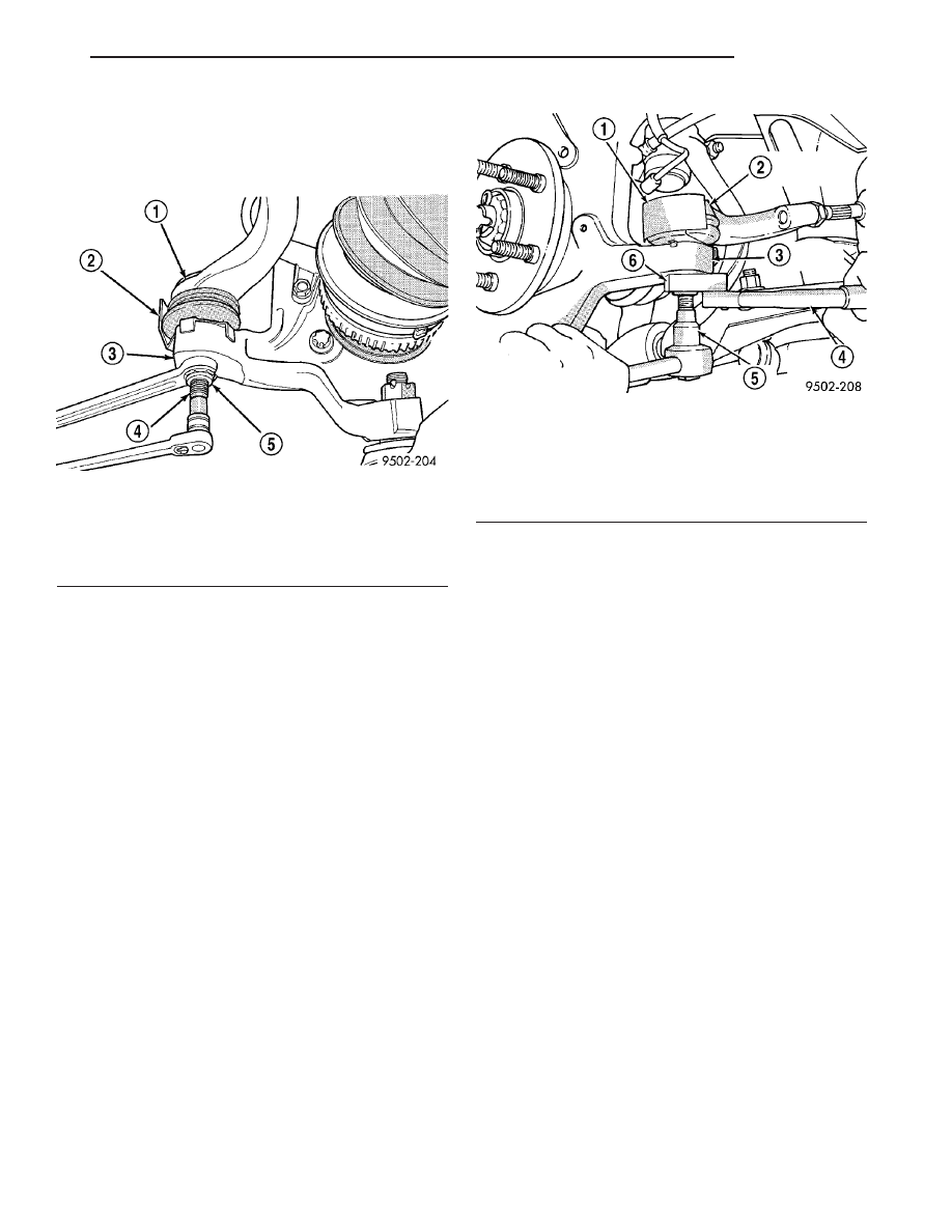
(4) Remove nut attaching outer tie rod to steering

knuckle (Fig. 18). Nut is removed from tie rod by
holding tie rod stud with a socket while loosen-
ing and removing nut with wrench.

(5) Remove tie rod stud from steering knuckle

using Remover, Special Tool C-3894-A.

(6) Remove outer tie rod from inner tie rod by un-

threading it.

INSTALLATION

(1) Thread outer tie rod onto inner tie rod. Make

sure jam nut is on inner tie rod before install-
ing outer tie rod. 
Do not tighten jam nut at this
time.

(2) Install tie rod end seal boot heat shield on the

tie rod end (Fig. 18).

(3) Install outer tie rod into steering knuckle.

Start tie rod-to-steering knuckle attaching nut onto
tie rod stud. While holding tie rod stud stationary
using a socket, use a crowfoot on a torque wrench to
tighten tie rod nut to 55 N·m (40 ft. lbs.) torque
(Fig. 19).

CAUTION: During the following step, do not allow
the steering gear boot to become twisted.

(4) Tighten tie rod jam nut (Fig. 17) to 75 N·m (55

ft. lbs.) torque.

(5) Install tire and wheel assembly. Progressively

tighten the wheel nuts in a criss-cross tightening
sequence to 135 N·m (100 ft. lbs.) torque.

(6) Lower vehicle.
(7) Adjust

front

wheel

alignment

toe

setting.

(Refer to 2 - SUSPENSION/WHEEL ALIGNMENT -
STANDARD PROCEDURE)

Fig. 18 Removing Outer Tie Rod Nut

1 - TIE ROD
2 - HEAT SHIELD
3 - STEERING KNUCKLE
4 - TIE ROD STUD
5 - NUT

Fig. 19 Torquing Tie Rod Nut

1 - HEAT SHIELD
2 - OUTER TIE ROD
3 - STEERING KNUCKLE
4 - TORQUE WRENCH
5 - 11/32 SOCKET
6 - CROWFOOT

JR

GEAR

19 - 27

TIE ROD - OUTER (Continued)

PUMP

TABLE OF CONTENTS

page

page

PUMP

DESCRIPTION

. . . . . . . . . . . . . . . . . . . . . . . . . 28

OPERATION

. . . . . . . . . . . . . . . . . . . . . . . . . . . 28

STANDARD PROCEDURE - POWER

STEERING PUMP INITIAL OPERATION

. . . . . 29

REMOVAL

REMOVAL - PUMP (2.0L/2.4L ENGINE)

. . . . . 29

REMOVAL - PUMP (2.7L ENGINE)

. . . . . . . . . 30

DISASSEMBLY - PUMP (PULLEY)

. . . . . . . . . . 31

ASSEMBLY - PUMP (PULLEY)

. . . . . . . . . . . . . 31

INSTALLATION

INSTALLATION - PUMP (2.0L/2.4L ENGINE)

. 32

INSTALLATION - PUMP (2.7L ENGINE)

. . . . . 33

FLUID

STANDARD PROCEDURE - POWER

STEERING FLUID LEVEL CHECKING

. . . . . . 33

HOSE - PRESSURE

REMOVAL

. . . . . . . . . . . . . . . . . . . . . . . . . . . . . 33

INSTALLATION

. . . . . . . . . . . . . . . . . . . . . . . . . 34

HOSE - RETURN

REMOVAL

. . . . . . . . . . . . . . . . . . . . . . . . . . . . . 34

INSTALLATION

. . . . . . . . . . . . . . . . . . . . . . . . . 36

HOSE - SUPPLY

REMOVAL

. . . . . . . . . . . . . . . . . . . . . . . . . . . . . 36

INSTALLATION

. . . . . . . . . . . . . . . . . . . . . . . . . 37

RESERVOIR

DESCRIPTION

. . . . . . . . . . . . . . . . . . . . . . . . . 37

REMOVAL

. . . . . . . . . . . . . . . . . . . . . . . . . . . . . 37

INSTALLATION

. . . . . . . . . . . . . . . . . . . . . . . . . 38

PUMP

DESCRIPTION

All vehicles are equipped with power steering. The

hydraulic pressure for operation of the power steer-
ing gear is provided by a belt driven power steering
pump (Fig. 1) (Fig. 2). The pump is a constant flow
rate and displacement vane type power steering
pump.

The power steering pump is mounted on the back

side of the engine, above the front suspension cross-
member.

The power steering pump uses a remote mounted

reservoir for storage of the power steering fluid.

Because of unique shaft bearings, flow control lev-

els or pump displacements, power steering pumps
may be used only on specific vehicle applications. Be
sure that the power steering pump is only replaced
with a pump that is the correct replacement for that
specific application.

OPERATION

Hydraulic pressure is provided for operation of the

power steering gear by the belt driven power steering
pump. The power steering pump is connected to the
steering gear by a power steering fluid pressure hose,
return hose, power steering fluid cooler and remote
power steering fluid reservoir.

Rectangular pumping vanes in the shaft driven

rotor move power steering fluid from the intake to
the cam ring pressure cavities of the power steering

pump. As the rotor begins to turn, centrifugal force
throws the vanes against the inside surface of the
cam ring to pick up residual oil. This oil is then
forced into the high pressure area. As more oil is
picked up by the vanes, the additional oil is forced
into the cavities of the thrust plate through two
crossover holes in the cam ring and pressure plate.
The crossover holes empty into the high pressure
area between the pressure plate and the housing end
cover.

Fig. 1 Power Steering Pump - 2.4L Engine

1 - SUPPLY FITTING
2 - PULLEY
3 - MOUNTING BRACKET
4 - PRESSURE FITTING

19 - 28

PUMP

JR

As the high pressure area is filled, oil flows under

the vanes in the rotor slots, forcing the vanes to fol-
low the inside surface of the cam ring. As the vanes
reach the restricted area of the cam ring, oil is forced
out from between the vanes. When excess oil flow is
generated during high-speed operation, a regulated
amount of oil returns to the pump intake side
through a flow control valve. The flow control valve
reduces the power required to drive the pump and
holds down temperature build-up.

When steering conditions exceed maximum pres-

sure requirements, such as when the wheels are
turned against the stops, the pressure built up in the
steering gear exerts pressure on the spring end of the
flow control valve inside the pump. The high pres-
sure lifts the relief valve ball from its seat and allows
oil to flow through a trigger orifice located in the out-
let fitting. This reduces pressure on the spring end of
the flow control valve which then opens and allows
the oil to return to the intake side of the pump. This
action limits maximum pressure output of the power
steering pump.

Under normal power steering pump operating con-

ditions, pressure requirements of the pump are below
maximum, causing the pressure relief valve to
remain closed.

In the event of a power steering pump drive belt

failure, manual steering control of the vehicle can
still be maintained without pump assistance. How-
ever, under these conditions, steering effort will be
significantly increased.

STANDARD PROCEDURE - POWER STEERING
PUMP INITIAL OPERATION

CAUTION: The fluid level should be checked with
engine off to prevent injury from moving compo-
nents. Use only Mopar

T

ATF+4 Automatic Transmis-

sion Fluid (MS-9602). Do not overfill.

(1) Wipe

the

reservoir

fill

cap

clean

before

removal.

(2) Fill the pump fluid reservoir to the proper

level. The fluid level should be within the “FILL
RANGE” listed on the exterior of the reservoir when
the fluid is at normal ambient temperature, approxi-
mately 21°C to 27°C (70°F to 80°F).

(3) Let the fluid settle in the system for at least

two (2) minutes.

(4) Start the engine and let run for a few seconds.

Then turn the engine off.

(5) Add fluid if necessary. Repeat the above proce-

dure until the fluid level remains constant after run-
ning the engine.

(6) Raise the front wheels off the ground.
(7) Start the engine. Slowly turn the steering

wheel right and left, lightly contacting the wheel
stops.

(8) Add power steering fluid if necessary.
(9) Lower the vehicle and turn the steering wheel

slowly from lock to lock.

(10) Stop the engine. Check the fluid level and

refill as required.

(11) If the fluid is extremely foamy, allow the vehi-

cle to stabilize a few minutes, then repeat the above
procedure.

REMOVAL

REMOVAL - PUMP (2.0L/2.4L ENGINE)

WARNING:

POWER

STEERING

FLUID,

ENGINE

COMPONENTS AND EXHAUST SYSTEM MAY BE
EXTREMELY HOT IF ENGINE HAS BEEN RUNNING.
DO NOT START ENGINE WITH ANY LOOSE OR DIS-
CONNECTED

HOSES,

OR

ALLOW

HOSES

TO

TOUCH HOT EXHAUST MANIFOLD OR CATALYST.

(1) Remove battery cable from negative (-) post on

battery and isolate cable.

(2) Siphon as much power steering fluid as possi-

ble out of the remote power steering fluid reservoir.

(3) Remove the clamp, then fluid supply hose from

fitting on pump. Install a cap on fitting.

(4) Raise vehicle. (Refer to LUBRICATION &

MAINTENANCE/HOISTING - STANDARD PROCE-
DURE)

(5) Remove the accessory drive splash shield.

Fig. 2 Power Steering Pump - 2.7L Engine

1 - SUPPLY FITTING
2 - PUMP SHAFT
3 - PULLEY
4 - PRESSURE FITTING

JR

PUMP

19 - 29

PUMP (Continued)

(6) Remove power steering fluid pressure hose

from pressure fitting on power steering pump (Fig.
3). Let power steering fluid drain out of system.
After power steering fluid has drained out of
pump and hose, install a cap on the power
steering pressure hose and a plug in the power
steering pump pressure fitting.

(7) Remove bolt at adjustment slot in pump front

mounting bracket.

(8) Remove nut at adjustment slot in cast alumi-

num mounting bracket at rear of pump.

(9) Loosen pump upper pivot bolt.
(10) Remove pump drive belt.
(11) Remove pump upper pivot bolt.
(12) Remove power steering pump and its front

mounting bracket as an assembly from the engine
through opening above right drive shaft and below
right frame rail.

(13) To remove the pulley or bracket, (Refer to 19 -

STEERING/PUMP - DISASSEMBLY).

REMOVAL - PUMP (2.7L ENGINE)

WARNING:

POWER

STEERING

FLUID,

ENGINE

COMPONENTS AND EXHAUST SYSTEM MAY BE

EXTREMELY HOT IF ENGINE HAS BEEN RUNNING.
DO NOT START ENGINE WITH ANY LOOSE OR DIS-
CONNECTED

HOSES,

OR

ALLOW

HOSES

TO

TOUCH HOT EXHAUST MANIFOLD OR CATALYST.

(1) Remove battery cable from (-) negative post on

battery and isolate cable.

(2) Siphon as much power steering fluid as possi-

ble out of power steering fluid reservoir.

(3) Remove power steering fluid supply hose from

power steering pump supply fitting (Fig. 4).

(4) Raise vehicle. (Refer to LUBRICATION &

MAINTENANCE/HOISTING - STANDARD PROCE-
DURE)

(5) Remove accessory drive splash shield.
(6) Remove power steering fluid pressure hose

from fitting on power steering pump (Fig. 4).

(7) Remove oxygen sensor harness and clip from

rear of pump.

(8) Completely remove bolt at slot in stamped

pump adjuster bracket (Fig. 5) and remove power
steering drive belt.

(9) Pivot pump out past full-adjust position. This

will allow access to two pump bracket-to-engine
mounting bolts.

Fig. 3 PUMP MOUNTING TO ENGINE

1 - DRIVE BELT
2 - PULLEY
3 - PRESSURE HOSE
4 - POWER STEERING PUMP
5 - SUPPLY HOSE

Fig. 4 Pump Mounting To Engine (2.7L)

1 - SUPPLY HOSE
2 - DRIVE BELT
3 - PULLEY
4 - PRESSURE HOSE
5 - POWER STEERING PUMP

19 - 30

PUMP

JR

PUMP (Continued)


Content   ..  555  556  557  558   ..