Chrysler Sebring, Stratus sedan, Sebring Convertible. Manual - part 531


  Index      Chrysler     Chrysler Sebring, Stratus sedan, Sebring Convertible - service repair manual 2001-2007 year


Search            


Content   ..  529  530  531  532   ..


Chrysler Sebring, Stratus sedan, Sebring Convertible. Manual - part 531


(6) Connect electrical connectors to the following

components:

• Manifold Absolute Pressure (MAP) Sensor

• Throttle Position Sensor (TPS) Sensor

• Idle Air Control (IAC) Motor
(7) Install throttle cable bracket.
(8) Connect throttle and speed control cables to

bracket and throttle arm. Install throttle cable
shield.

(9) Install throttle body air inlet hose and air

cleaner housing assembly.

(10) Connect negative battery cable.

INSTALLATION - INTAKE MANIFOLD LOWER

(1) Clean and inspect sealing surfaces of cylinder

head and manifold. Gaskets can be reused provided
they are free of cuts or tears.

(2) Position manifold on cylinder head surfaces.

NOTE: For ease of installing upper intake manifold,
install a bolt 2 – 3 turns to the rearmost attaching
hole of intake. This will properly position lower
manifold.

(3) Install fuel rail with injectors.
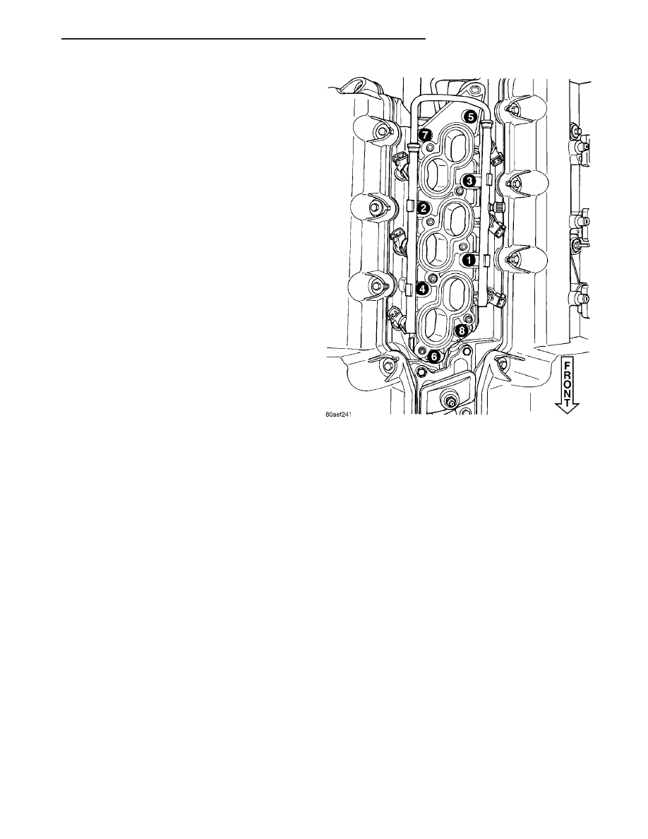
(4) Install manifold attaching bolts and tighten in

sequence shown in (Fig. 111) to 12 N·m (105 in. lbs.).
Remove bolt used for aligning manifold.

(5) Connect the fuel injector electrical connectors.

NOTE: Make sure fuel injectors are located in the
correct location and position, as upper intake man-
ifold interference could occur.

(6) Install

screw

attaching

fuel

rail

support

bracket to the throttle body support bracket.

(7) Connect fuel supply hose to fuel rail. (Refer to

14 - FUEL SYSTEM/FUEL DELIVERY/FUEL LINES
- STANDARD PROCEDURE)

(8) Install upper intake manifold. (Refer to 9 -

ENGINE/MANIFOLDS/INTAKE

MANIFOLD

-

INSTALLATION)

EXHAUST MANIFOLD

REMOVAL

FRONT EXHAUST MANIFOLD

(1) Disconnect negative battery cable.
(2) Disconnect and remove oxygen sensor.
(3) Raise vehicle on hoist.
(4) Remove exhaust cross-under pipe (Refer to 11 -

EXHAUST

SYSTEM/CROSS-OVER

PIPE

-

REMOVAL).

(5) Remove front catalytic converter (Refer to 11 -

EXHAUST SYSTEM/CATALYTIC CONVERTER -
REMOVAL).

(6) Lower vehicle.
(7) Remove exhaust manifold attaching bolts and

remove manifold.

REAR EXHAUST MANIFOLD

(1) Disconnect negative battery cable.
(2) Remove throttle body air inlet hose and air

cleaner housing assembly.

(3) Remove bolts attaching EGR tube from exhaust

manifold and EGR valve. Discard gaskets.

(4) Raise vehicle on hoist.
(5) Remove exhaust system from vehicle (Refer to

11 - EXHAUST SYSTEM - REMOVAL).

(6) Remove exhaust cross-under pipe (Refer to 11 -

EXHAUST

SYSTEM/CROSS-OVER

PIPE

-

REMOVAL).

(7) Remove rear catalytic converter (Refer to 11 -

EXHAUST SYSTEM/CATALYTIC CONVERTER -
REMOVAL).

(8) Disconnect and remove rear upstream oxygen

sensor.

(9) Remove rear exhaust manifold heat shield.
(10) Remove exhaust manifold attaching bolts and

remove manifold.

Fig. 111 Lower Intake Manifold Tightening Sequence

JR

ENGINE 2.7L DOHC

9 - 227

INTAKE MANIFOLD (Continued)

INSPECTION

(1) Inspect

exhaust

manifolds

for

damage

or

cracks.

(2) Check manifold flatness.
(3) Inspect the exhaust manifold gasket for obvi-

ous discoloration or distortion.

(4) Check distortion of the cylinder head mounting

surface with a straightedge and thickness gauge.

INSTALLATION

FRONT EXHAUST MANIFOLD

(1) Install exhaust manifold and gasket. Tighten

bolts starting at the center working outward to 23
N·m (200 in. lbs.).

(2) Raise vehicle on hoist.
(3) Install front catalytic converter and manifold

heat shield. Tighten fasteners to 28 N·m (250 in. lbs.)
(Refer to 11 - EXHAUST SYSTEM/CATALYTIC
CONVERTER - INSTALLATION).

(4) Install exhaust cross-under pipe. Tighten fas-

teners to 28 N·m (250 in. lbs.) (Refer to 11 -
EXHAUST SYSTEM/CROSS-OVER PIPE - INSTAL-
LATION).

(5) Lower vehicle.
(6) Install oxygen sensor and connect electrical

connector.

(7) Connect negative battery cable.

REAR EXHAUST MANIFOLD

(1) Install exhaust manifold and gasket. Tighten

bolts working from center outwards to 23 N·m (200
in. lbs.).

(2) Install rear catalytic converter and manifold

heat shield. Tighten fasteners to 28 N·m (250 in. lbs.)
(Refer to 11 - EXHAUST SYSTEM/CATALYTIC
CONVERTER - INSTALLATION).

(3) Install oxygen sensor and connect electrical

connector.

(4) Install exhaust cross-under pipe. Tighten fas-

teners to 28 N·m (250 in. lbs.) (Refer to 11 -
EXHAUST SYSTEM/CROSS-OVER PIPE - INSTAL-
LATION).

(5) Install exhaust system. Tighten fasteners to 28

N·m (250 in. lbs.) (Refer to 11 - EXHAUST SYSTEM
- INSTALLATION).

(6) Lower vehicle.
(7) Install EGR tube using new gaskets. Tighten

screws to 11 N·m (95 in. lbs.).

(8) Install throttle body air inlet hose and air

cleaner housing assembly.

(9) Connect negative battery cable.

VALVE TIMING

DESCRIPTION

The timing drive system has been designed to pro-

vide quiet performance and reliability to support a
NON free-wheeling engine. The system consists of a
primary and secondary chain drive.

The primary timing chain drive (Fig. 112) uses a

single, double-flexure, inverted tooth type chain. The
primary chain drives both of the intake camshafts
directly from a sprocket mounted on the crankshaft.
In addition, the water pump is driven by the “back
side” of the primary chain, necessitating the double-
flexure type chain.

The chain is controlled by three fixed chain guides

and a pivoting tensioner arm (Fig. 112). These guides
utilize low-friction and long wearing nylon plastic
wear faces. To tension the primary chain, a fully
automatic spring-loaded, engine oil-fed, hydraulic
tensioner is used. The tensioner is mounted in the
right cylinder head with the plunger contacting the
pivoting tensioner arm. A mechanical ratchet mecha-
nism inside the tensioner prevents excessive chain
slack upon engine start-up as the chain wears. The
tensioner is designed with an internal oil reservoir to
assure noise-free performance, even during engine
start-up before oil pressure reaches the tensioner.

For lubrication the primary chain utilizes oil leak-

age from the front of the oil pump. This oil spills on
the crankshaft sprocket, which is then carried by the
chain throughout the primary drive.

The secondary timing chain drive system uses

two conventional roller-type chains, one at each cyl-
inder bank (Fig. 25). The purpose of the secondary
chain is to provide a mechanical driven connection
between the intake and exhaust camshafts. The
intake camshafts drive the exhaust camshafts. The
sprockets for both intake and exhaust camshafts are
a press-fit and are only serviced as an assembly with
the camshafts.

To tension the secondary chain a spring-loaded,

hydraulic tensioner is used at each bank and
attaches to each cylinder head between the intake
and exhaust camshafts (Fig. 25). The tensioner incor-
porates upper and lower chain guide faces. The lower
guide face is attached directly to the tensioner’s
hydraulic plunger. Also, the tensioner uses an inter-
nal oil reservoir design to prevent engine start-up
noise. The secondary chains are lubricated via an oil
passage through the upper guide face on each ten-
sioner.

9 - 228

ENGINE 2.7L DOHC

JR

EXHAUST MANIFOLD (Continued)

Fig. 112 TIMING DRIVE SYSTEM

1 – CAMSHAFT DAMPER (IF EQUIPPED)

7 – CHAIN GUIDE

2 – CHAIN GUIDE

8 – CHAIN TENSIONER ARM

3 – ACCESS PLUG

9 – CHAIN TENSIONER

4 – CAMSHAFT POSITION SENSOR

10 – CAMSHAFT SPROCKETS

5 – PRIMARY TIMING CHAIN

11 – CHAIN GUIDE

6 – CRANKSHAFT SPROCKET

JR

ENGINE 2.7L DOHC

9 - 229

VALVE TIMING (Continued)

STANDARD PROCEDURE

ENGINE TIMING - VERIFICATION

Correct timing is critical for the NON free-wheel-

ing designed, 2.7L engine. Engine timing can be ver-
ified by using the following procedures:

(1) Remove cylinder head covers. (Refer to 9 -

ENGINE/CYLINDER

HEAD/CYLINDER

HEAD

COVER(S) - REMOVAL)

(2) Rotate engine until number one cylinder is at

TDC on the EXHAUST stroke.

(3) View the intake camshaft sprocket timing

mark. The mark should be 90° from the cylinder
head cover sealing surface (Fig. 113)on both right
and left cylinder banks.

(4) Count chain pins from the mark on the intake

camshaft towards the exhaust camshaft. Engine is
timed correctly when there are 12 chain pins
between the timing marks on the intake camshaft
and exhaust camshaft (Fig. 113).

(5) If marks are not correctly aligned, proceed to

Timing Chain and Sprockets for service procedures.
(Refer to 9 - ENGINE/VALVE TIMING/TIMING
BELT/CHAIN AND SPROCKETS - REMOVAL)

TIMING CHAIN COVER

REMOVAL

(1) Disconnect negative battery cable.
(2) Drain cooling system (Refer to 7 - COOLING/

ENGINE - STANDARD PROCEDURE).

(3) Remove coolant pressure container (Refer to 7 -

COOLING/ENGINE/COOLANT RECOVERY PRESS
CONTAINER - REMOVAL).

(4) Raise vehicle on hoist.
(5) Remove right front wheel and belt splash

shield.

(6) Remove accessory drive belts (Refer to 7 -

COOLING/ACCESSORY

DRIVE/DRIVE

BELTS

-

REMOVAL).

(7) Remove crankshaft vibration dampner (Refer to

9

-

ENGINE/ENGINE

BLOCK/VIBRATION

DAMPER - REMOVAL).

(8) Remove AC/Generator belt tensioner/bracket

assembly.

(9) Disconnect heater hose from tube at right front

frame rail area.

(10) Lower vehicle.

Fig. 113 ENGINE TIMING

1 - 12 PINS

3 - 12 PINS

2 - CAMSHAFT TIMING MARKS

9 - 230

ENGINE 2.7L DOHC

JR

VALVE TIMING (Continued)


Content   ..  529  530  531  532   ..