Chrysler Sebring, Stratus sedan, Sebring Convertible. Manual - part 529


  Index      Chrysler     Chrysler Sebring, Stratus sedan, Sebring Convertible - service repair manual 2001-2007 year


Search            


Content   ..  527  528  529  530   ..


Chrysler Sebring, Stratus sedan, Sebring Convertible. Manual - part 529


PRESSURE CONTROL VALVE

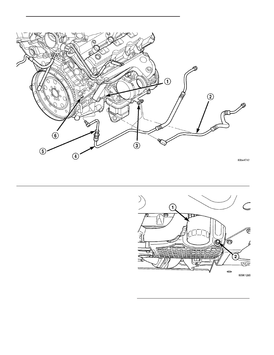
(1) Install supply line fitting into engine block

(Fig. 93). Tighten fitting to 30 N·m (260 in. lbs.).

(2) Position control valve into fitting. Push valve

into fitting until it locks in place. Ensure proper con-
nection is made by pulling in-and-out on valve.

(3) Connect supply line to control valve. Tighten

connection fitting to 30 N·m (260 in. lbs.).

OIL FILTER

REMOVAL

(1) Raise vehicle on hoist.
(2) Position a suitable collecting container under

oil filter location (Fig. 94).

(3) Remove oil filter using a suitable oil filter

wrench (Fig. 94). Dispose of oil filter following envi-
romental guidelines.

INSTALLATION

(1) Wipe filter base clean, then inspect gasket seal-

ing surface.

(2) Lubricate gasket of new filter with clean

engine oil.

(3) Install oil filter (Fig. 94) and tighten to 16 N·m

(12 ft. lbs.) of torque after gasket contacts base. Use
filter wrench if necessary.

(4) Fill crankcase with proper engine oil to correct

level if drained. Start engine and check for leaks.

Fig. 93 Engine Oil Cooler Lines—2.7L

1 - RETURN LINE FITTING
2 - OIL COOLER RETURN LINE
3 - SUPPORT BRACKET

4 - OIL COOLER SUPPLY LINE
5 - PRESSURE CONTROL VALVE
6 - SUPPLY LINE FITTING

Fig. 94 Engine Oil Filter

1 - OIL FILTER
2 - OIL DRAIN PLUG

JR

ENGINE 2.7L DOHC

9 - 219

OIL COOLER & LINES (Continued)

OIL PAN

REMOVAL

(1) Disconnect negative battery cable.
(2) Remove engine oil dipstick and tube.
(3) Raise vehicle on hoist.
(4) Drain engine oil and remove oil filter.
(5) Remove structural collar (Fig. 95) (Refer to 9 -

ENGINE/ENGINE BLOCK/STRUCTURAL COVER -
REMOVAL).

(6) Remove exhaust cross-under pipe (Refer to 11 -

EXHAUST

SYSTEM/CROSS-OVER

PIPE

-

REMOVAL).

(7) Remove torque converter housing cover.
(8) Remove lower bolt attaching the A/C compres-

sor to oil pan.

CAUTION: Assure removal of the two bolts attach-
ing the timing cover to the oil pan, as damage to
the timing cover and/or oil pan may occur.

(9) Remove oil pan attaching fasteners. Remove oil

pan and gasket (Fig. 96).

INSTALLATION

(1) Clean oil pan and sealing surfaces. Inspect oil

pan and timing chain cover gaskets. Replace as nec-
essary.

(2) Apply an 1/8 inch bead of Mopar

t Engine RTV

GEN II to the front T-joints (oil pan gasket to timing
cover gasket interface) and the rear T-joints (oil pan
gasket to crankshaft rear oil seal retainer gasket
interface) (Fig. 96).

(3) Install oil pan gasket to block.

NOTE: To prevent oil leaks at oil pan to timing
chain cover, the following tightening sequence pro-
cedure must be performed.

(4) Install oil pan and fasteners (Fig. 96) using the

following tightening sequence:

(a) Install oil pan bolts and nuts finger tight

only—just tight enough to compress the gas-
ket’s rubber seal
.

(b) Install timing chain cover to pan bolts and

tighten to 12 N·m (105 in. lbs.).

(c) Tighten oil pan bolts to 28 N·m (250 in. lbs.).
(d) Tighten oil pan nuts to 12 N·m (105 in. lbs.).

(5) Install lower bolt attaching the A/C compressor

to oil pan. Tighten bolt to 28 N·m (21 ft. lbs.).

(6) Install torque converter housing cover.
(7) Install oil filter and drain plug.
(8) Install exhaust cross-under pipe (Refer to 11 -

EXHAUST SYSTEM/CROSS-OVER PIPE - INSTAL-
LATION).

(9) Install structural collar (Fig. 95) (Refer to 9 -

ENGINE/ENGINE BLOCK/STRUCTURAL COVER -
INSTALLATION).

(10) Lower vehicle.
(11) Install engine oil dipstick and tube.
(12) Fill engine crankcase with proper oil to cor-

rect level.

(13) Connect negative battery cable.

Fig. 95 Structural Collar (Note: cross-under pipe not

shown)

1 - STRUCTURAL COLLAR
2 - BOLT (2) - COLLAR TO TRANSAXLE
3 - BOLT (2) - COLLAR TO OIL PAN

Fig. 96 Oil Pan and Sealing

1 - SEALER LOCATION
2 - BOLT-M6
3 - GASKET
4 - NUT-M6
5 - OIL PAN
6 - BOLT-M8
7 - NUT-M6

9 - 220

ENGINE 2.7L DOHC

JR

OIL PRESSURE RELIEF VALVE

REMOVAL

(1) Remove the oil pan. (Refer to 9 - ENGINE/LU-

BRICATION/OIL PAN - REMOVAL)

(2) Remove the pressure relief valve by remove the

threaded retaining cap from the oil pump housing.

CAUTION: Oil pump pressure relief valve must be
installed as shown in (Fig. 97) or engine damage
may occur.

(3) Remove spring and relief valve (Fig. 97).

INSTALLATION

(1) Lubricate relief valve with oil.

CAUTION:

The

pressure

relief

valve

must

be

installed as shown in (Fig. 97), or engine damage
may occur.

(2) Install relief valve, spring and retainer cap

(Fig. 97). Tighten cap to 12 N·m (105 in. lbs.).

(3) Install the oil pan. (Refer to 9 - ENGINE/LU-

BRICATION/OIL PAN - INSTALLATION)

OIL PRESSURE SWITCH

DESCRIPTION

The engine oil pressure switch is located on the

right side of the engine block. The switch screws into
the engine main oil gallery. The normally closed
switch provides an input through a single wire to the
low pressure indicator light on the instrument clus-
ter.

REMOVAL

(1) Raise vehicle on hoist.
(2) Remove heat shield that covers oil pressure

switch.

(3) Disconnect oil pressure switch electrical con-

nector.

(4) Position

an

oil

collecting

container

under

switch location.

(5) Remove switch by unscrewing from the engine

block.

INSTALLATION

(1) Apply Mopar

t Thread Sealant to the switch

threads.

(2) Install oil pressure switch.
(3) Connect electrical connector.
(4) Install oil pressure switch heat shield.
(5) Lower vehicle.
(6) Start engine and check for leaks.
(7) Check engine oil level and adjust as neccessary.

OIL PUMP

REMOVAL

The oil pump pressure relief valve can be serviced

by removing the oil pan.

(1) Remove crankshaft vibration damper. (Refer to

9

-

ENGINE/ENGINE

BLOCK/VIBRATION

DAMPER - REMOVAL)

(2) Remove timing chain cover. (Refer to 9 -

ENGINE/VALVE TIMING/TIMING BELT / CHAIN
COVER(S) - REMOVAL)

(3) Remove timing chain and sprockets. (Refer to 9

- ENGINE/VALVE TIMING/TIMING BELT/CHAIN
AND SPROCKETS - REMOVAL)

(4) Remove oil pan. (Refer to 9 - ENGINE/LUBRI-

CATION/OIL PAN - REMOVAL)

(5) Remove oil pick-up tube and O-ring (Fig. 99).
(6) Ensure that crankshaft position is at 60° ATDC

of No.1 cylinder, or crankshaft sprocket mark aligns
with mark on oil pump (Fig. 98). This position will
properly locate oil pump upon installation.

(7) Remove oil pump attaching bolts (Fig. 99).
(8) Remove oil pump.

Fig. 97 Oil Pressure Relief Valve

1 - RELIEF VALVE
2 - SPRING
3 - RETAINER CAP

JR

ENGINE 2.7L DOHC

9 - 221

DISASSEMBLY

(1) Remove the pressure relief valve by remove the

threaded retaining cap from the oil pump housing.

CAUTION: Oil pump pressure relief valve must be
installed as shown in (Fig. 100) or engine damage
may occur.

(2) Remove spring and relief valve.

(3) Remove oil pump cover screws and lift off cover

plate (Fig. 101).

(4) Remove pump rotors.
(5) Wash all parts in a suitable solvent.
(6) Inspect components carefully for damage or

wear. (Refer to 9 - ENGINE/LUBRICATION/OIL
PUMP - INSPECTION)

CLEANING

(1) Clean all parts thoroughly in a suitable sol-

vent.

INSPECTION

(1) Disassemble the oil pump. (Refer to 9 -

ENGINE/LUBRICATION/OIL PUMP - DISASSEM-
BLY)

(2) Clean all oil pump components. (Refer to 9 -

ENGINE/LUBRICATION/OIL PUMP - CLEANING)

(3) Inspect mating surface of the oil pump housing

and cover. Replace oil pump if deeply scratched or
grooved (minor surface scratches and polishing is
normal).

Fig. 98 Crankshaft Positioned At 60 DEGREES

ATDC No.1 Cylinder

1 - CRANKSHAFT POSITION = 60° ATDC NO. 1 CYLINDER

Fig. 99 Oil Pump and Pick-up Tube

1 - BOLTS
2 - O-RING
3 - PICK-UP TUBE
4 - BOLT
5 - OIL PUMP

Fig. 100 Oil Pressure Relief Valve

1 - RELIEF VALVE
2 - SPRING
3 - RETAINER CAP

9 - 222

ENGINE 2.7L DOHC

JR

OIL PUMP (Continued)


Content   ..  527  528  529  530   ..