Chrysler Sebring, Stratus sedan, Sebring Convertible. Manual - part 530
 

  Index      Chrysler     Chrysler Sebring, Stratus sedan, Sebring Convertible - service repair manual 2001-2007 year


Search            


Content   ..  528  529  530  531   ..


Chrysler Sebring, Stratus sedan, Sebring Convertible. Manual - part 530


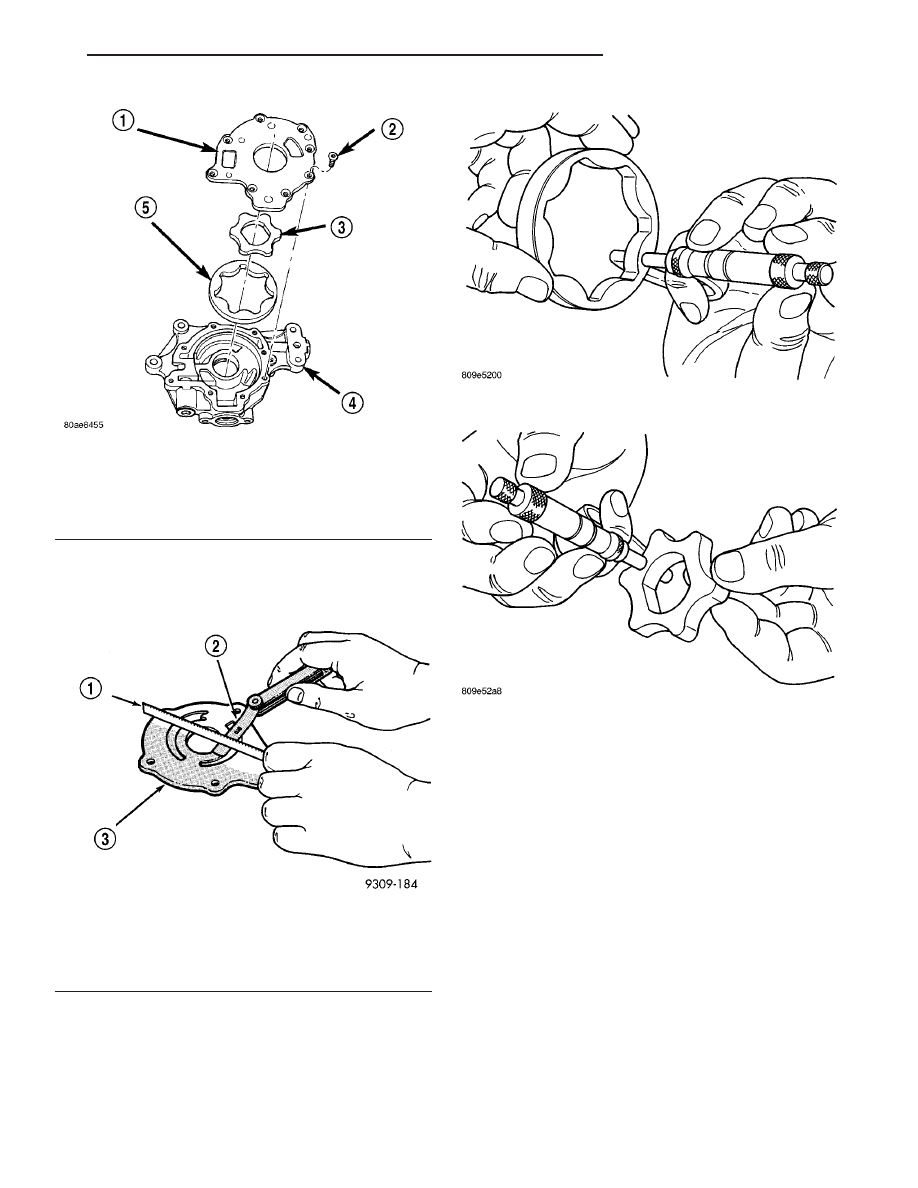
(4) Lay a straightedge across the pump cover sur-

face (Fig. 102). If a 0.025 mm (0.001 in.) feeler gauge
can be inserted between cover and straight edge,
cover should be replaced.

(5) Measure thickness and diameter of outer rotor.

If outer rotor thickness measures 9.474 mm (0.373
in.) or less (Fig. 103), or if the diameter is 89.174 mm
(3.5108 in.) or less, replace outer rotor.

(6) If inner rotor measures 9.474 mm (0.373 in.) or

less replace inner rotor (Fig. 104).

(7) Slide outer rotor into body, press to one side

with fingers and measure clearance between rotor
and body (Fig. 105). If measurement is 0.39 mm
(0.015 in.) or more, replace body only if outer rotor is
in specifications.

(8) Install inner rotor into body. If clearance

between inner and outer rotors (Fig. 106) is 0.20 mm
(0.008 in.) or more, replace both rotors.

(9) Place a straightedge across the face of the body,

between bolt holes. If a feeler gauge of 0.077 mm
(0.003 in.) or more can be inserted between rotors
and the straightedge, replace pump assembly (Fig.
107) ONLY if rotors are in specification.

(10) Inspect oil pressure relief valve plunger for

scoring and free operation in its bore. Small marks
may be removed with 400-grit wet or dry sandpaper.

(11) The relief valve spring has a free length of

approximately 49.5 mm (1.95 in.) it should test
between 23 – 25 pounds when compressed to 34 mm
(1.34 in.). Replace spring that fails to meet specifica-
tions.

Fig. 101 Oil Pump

1 - OIL PUMP COVER
2 - SCREWS (8)
3 - OIL PUMP INNER ROTOR
4 - OIL PUMP HOUSING
5 - OIL PUMP OUTER ROTOR

Fig. 102 CHECKING OIL PUMP COVER FLATNESS -

TYPICAL

1 - STRAIGHT EDGE
2 - FEELER GAUGE
3 - OIL PUMP COVER

Fig. 103 MEASURING OUTER ROTOR THICKNESS

Fig. 104 MEASURING INNER ROTOR THICKNESS

JR

ENGINE 2.7L DOHC

9 - 223

OIL PUMP (Continued)

(12)

Assemble oil pump. (Refer to 9 - ENGINE/

LUBRICATION/OIL PUMP - ASSEMBLY)

ASSEMBLY

(1) Assemble pump using new parts as required.
(2) Tighten cover screws to 12 N·m (105 in. lbs.)

(Fig. 101).

(3) Tighten oil pressure relief valve retaining cap

to 12 N·m (105 in. lbs.) (Fig. 100).

(4) Prime oil pump before installation by filling

rotor cavity with engine oil.

INSTALLATION

CAUTION: Crankshaft position must be at 60° ATDC
of No.1 cylinder before installing oil pump (Fig. 98).
This position will properly locate oil pump. If not
properly located, severe damage to oil pump can
occur.

(1) Prime oil pump before installation by filling

rotor cavity with engine oil.

(2) If crankshaft has been rotated, it must be repo-

sitioned to 60° ATDC of No.1 cylinder prior to oil
pump installation (Fig. 98).

(3) Install oil pump carefully over crankshaft and

into position.

(4) Install oil pump attaching bolts. Tighten bolts

to 28 N·m (250 in. lbs.) (Fig. 99).

(5) Install oil pick-up tube with new O-ring. Lubri-

cate O-ring before installation. Tighten attaching
bolts to 28 N·m (250 in. lbs.) (Fig. 99).

(6) Install oil pan. (Refer to 9 - ENGINE/LUBRI-

CATION/OIL PAN - INSTALLATION)

(7) Install timing chain and sprockets. (Refer to 9 -

ENGINE/VALVE

TIMING/TIMING

BELT/CHAIN

AND SPROCKETS - INSTALLATION)

(8) Install timing chain cover. (Refer to 9 -

ENGINE/VALVE TIMING/TIMING BELT / CHAIN
COVER(S) - INSTALLATION)

(9) Install crankshaft vibration damper. (Refer to 9

- ENGINE/ENGINE BLOCK/VIBRATION DAMPER -
INSTALLATION)

(10) Fill crankcase with engine oil to correct level.

Fig. 105 MEASURING OUTER ROTOR CLEARANCE

IN HOUSING

1 - FEELER GAUGE
2 - OUTER ROTOR

Fig. 106 MEASURING CLEARANCE BETWEEN

ROTORS

1 - OUTER ROTOR
2 - FEELER GAUGE
3 - INNER ROTOR

Fig. 107 MEASURING CLEARANCE OVER ROTORS

1 - STRAIGHT EDGE
2 - FEELER GAUGE

9 - 224

ENGINE 2.7L DOHC

JR

OIL PUMP (Continued)

INTAKE MANIFOLD

DIAGNOSIS AND TESTING

INTAKE MANIFOLD LEAKS

An intake manifold air leak is characterized by

lower than normal manifold vacuum. Also, one or
more cylinders may not be functioning.

WARNING: USE EXTREME CAUTION WHEN THE
ENGINE IS OPERATING. DO NOT STAND IN A
DIRECT LINE WITH THE FAN. DO NOT PUT YOUR
HANDS NEAR THE PULLEYS, BELTS OR THE FAN.
DO NOT WEAR LOOSE CLOTHING.

(1) Start the engine.
(2) Spray a small stream of water (Spray Bottle) at

the suspected leak area.

(3) If engine RPM’S change, the area of the sus-

pected leak has been found.

(4) Repair as required.

STANDARD PROCEDURE - INTAKE MANIFOLD
VACUUM PORT REPAIR

The composite intake manifold vacuum ports can

be repaired. Although, if the manifold plenum cham-
ber is damaged or cracked, the manifold must be
replaced.

To repair a broken or damaged vacuum nipple

(port) on the composite intake manifold, perform the
following procedure:

PARTS REQUIRED

TOOLS REQUIRED

Brass Nipple – 3/8

9

O.D.

x 1/4

9

pipe thread (Speed

Control Port)

Pipe Tap – 1/4

9

- 18 NPT

Brass Nibble – 1/2

9

O.D.

x 1/4

9

pipe thread (Brake

Booster Port)

Drill Bit – 7/16

9

File/Sand Paper

NOTE: While performing this procedure, avoid get-
ting the manifold material residue into the plenum
chamber.

(1) File or sand the remaining port back until a

flat surface is obtained (plane normal to nipple (port)
axis).

(2) Drill out the nipple (port) base using a 7/16”

drill bit (Fig. 108).

(3) Using a 1/4”–18 NPT pipe tap, cut internal

threads (Fig. 108). Use caution to start tap in a axis
same as original nipple.

(4) Apply Mopar

t Thread Sealant to threads of

repair nipple(s).

(5) Install repair nipple(s). Do not over torque

repair nipple(s).

REMOVAL

REMOVAL - INTAKE MANIFOLD UPPER

(1) Disconnect negative battery cable.
(2) Remove throttle body air inlet hose and air

cleaner housing assembly.

(3) Remove throttle cable shield. Remove throttle

and speed control cables from throttle arm and
bracket.

(4) Remove throttle cable bracket.
(5) Disconnect electrical connectors from the fol-

lowing components:

• Manifold Absolute Pressure (MAP) Sensor

• Throttle Position Sensor (TPS) Sensor

• Idle Air Control (IAC) Motor
(6) Disconnect Vapor Purge hose, Brake Booster

hose, Speed Control Servo, Positive Crankcase Venti-
lation (PCV) hose.

(7) Loosen upper fastener at throttle body support

bracket.

(8) Remove manifold attaching bolts (Fig. 110).
(9) Remove upper manifold (Fig. 109).
(10) Inspect manifold. (Refer to 9 - ENGINE/MAN-

IFOLDS/INTAKE MANIFOLD - INSPECTION)

REMOVAL - INTAKE MANIFOLD LOWER

(1) Release fuel system pressure. (Refer to 14 -

FUEL SYSTEM/FUEL DELIVERY - STANDARD
PROCEDURE)

Fig. 108 MANIFOLD PORT (NIPPLE) REPAIR

1 - 1/4” — 18NPT PIPE TAP
2 - NIPPLE (PORT)

JR

ENGINE 2.7L DOHC

9 - 225

(2) Remove upper intake manifold. (Refer to 9 -

ENGINE/MANIFOLDS/INTAKE

MANIFOLD

-

REMOVAL)

(3) Disconnect electrical connectors from the fuel

injectors.

(4) Remove fuel supply hose from fuel rail. (Refer

to 14 - FUEL SYSTEM/FUEL DELIVERY/FUEL
LINES - STANDARD PROCEDURE)

(5) Remove

screw

attaching

fuel

rail

support

bracket to the throttle body support bracket.

(6) Remove bolts attaching fuel rail.
(7) Remove fuel rail and injectors as an assembly.
(8) Remove manifold attaching bolts (Fig. 111).
(9) Remove lower manifold.
(10) Inspect manifold. (Refer to 9 - ENGINE/MAN-

IFOLDS/INTAKE MANIFOLD - INSPECTION)

INSPECTION

INSPECTION - INTAKE MANIFOLD UPPER

Check manifold for:
• Damage and cracks

• Gasket surface damage or warpage

• Damaged or clogged EGR ports
If the manifold exihibits any damaged or warped

conditions, replace the manifold. Clean EGR ports as
neccessary.

If a vacuum port is damaged, a repair procedure

can be performed (Refer to 9 - ENGINE/MANI-

FOLDS/INTAKE MANIFOLD - STANDARD PROCE-
DURE).

INSPECTION - INTAKE MANIFOLD LOWER

Check manifold for:
• Damage and cracks

• Gasket surface damage or warpage

• Damaged fuel injector ports
If the manifold exihibits any of these conditions,

replace the manifold.

INSTALLATION

INSTALLATION - INTAKE MANIFOLD UPPER

(1) Clean and inspect sealing surfaces. Gaskets

can be reused, if free of cuts or tears.

NOTE: Make sure fuel injectors and wiring har-
nesses are in correct position to not interfere with
upper manifold installation.

(2) Position upper manifold onto lower manifold

(Fig. 109).

(3) Install manifold attaching bolts and tighten in

sequence shown in (Fig. 110) to 12 N·m (105 in. lbs.).

(4) Tighten upper fastener at throttle body support

bracket.

(5) Connect speed control servo, PCV , brake

booster, and vapor purge hoses.

Fig. 109 INTAKE MANIFOLD - UPPER

1 - BOLT
2 - INTAKE MANIFOLD - UPPER

Fig. 110 Upper Intake Manifold Tightening Sequence

9 - 226

ENGINE 2.7L DOHC

JR

INTAKE MANIFOLD (Continued)


Content   ..  528  529  530  531   ..