Chrysler Sebring, Stratus sedan, Sebring Convertible. Manual - part 527


  Index      Chrysler     Chrysler Sebring, Stratus sedan, Sebring Convertible - service repair manual 2001-2007 year


Search            


Content   ..  525  526  527  528   ..


Chrysler Sebring, Stratus sedan, Sebring Convertible. Manual - part 527


FROM:

TO:

FROM:

TO:

Oil Pump

Oil Filter Mounting (inlet)

Main Oil Gallery - Center
of Block

1. Crankshaft Main
Bearings

Oil Filter Mounting (inlet)

Oil Filter

2. Left Cylinder Head*

Oil Filter

Oil Filter Mounting (outlet)

3. Right Cylinder Head*

Oil Filter Mounting (outlet)

Oil Gallery - Right side of
Block

Crankshaft Main Bearings

Connecting Rod Bearings

Oil Gallery - Right side of
Block

Oil Gallery - Rear of Block
and to Oil Cooler (some
models)

Left Cylinder Head

Refer to 87

Oil Gallery - Rear of Block

Main Oil Gallery - Center
of Block

Right Cylinder Head

Refer to 88

*The cylinder head gaskets have an oil restrictor to control oil flow to the cylinder heads.

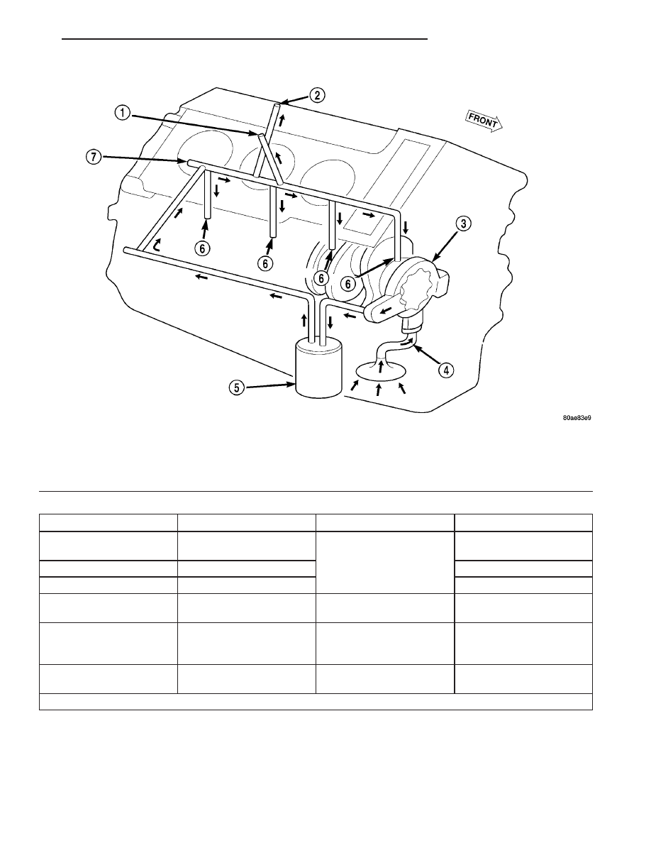
Fig. 86 Cylinder Block Oil Lubrication System

1 - TO RIGHT CYLINDER HEAD

5 - OIL FILTER

2 - TO LEFT CYLINDER HEAD

6 - TO CRANKSHAFT MAIN JOURNALS

3 - OIL PUMP

7 - MAIN OIL GALLERY

4 - OIL PICKUP TUBE

JR

ENGINE 2.7L DOHC

9 - 211

LUBRICATION (Continued)

FROM:

TO:

Left Cylinder Head Oil Inlet Gallery (intake side of
head)

Oil Gallery and Accumulator – Rear of Head*

Oil Gallery and Accumulator – Rear of Head*

1. Exhaust Camshaft Oil Passage

2. Intake Camshaft Oil Passage

Left Exhaust Camshaft Oil Passage

1. Left Exhaust Camshaft Journals

2. Hydraulic Valve Lash Adjusters and Rocker Arms

3. Left Camshaft (Secondary) Chain Tensioner**

Left Intake Camshaft Oil Passage

1. Left Intake Camshaft Journals

2. Hydraulic Valve Lash Adjusters and Rocker Arms

* When oil reaches the back of the cylinder head, the oil gallery feeds oil into an accumulator chamber that is
located towards center of the head. The accumulator chamber is closed off with a pressed in core plug that has a
small orifice to act as a vent. Oil then travels down at a 45 degree angle from the accumulator into two passages,
one for the intake and one for the exhaust side of the cylinder head.

** The secondary camshaft chain tensioner is the last component to receive oil on the left cylinder head.

Fig. 87 Cylinder Head Oil Lubrication System - Left Side

1 - CAM JOURNALS

4 - OIL FEED FROM BLOCK

2 - OIL FEED TO CAMSHAFT (SECONDARY) CHAIN TENSIONER

5 - VENT HOLE

3 - LASH ADJUSTER BORES

6 - ACCUMULATOR

9 - 212

ENGINE 2.7L DOHC

JR

LUBRICATION (Continued)

FROM:

TO:

Right Cylinder Head Oil Inlet Gallery (intake side of
head)

Oil Gallery and Accumulator – Rear of Head*

Oil Gallery and Accumulator – Rear of Head*

1. Exhaust Camshaft Oil Passage

2. Intake Camshaft Oil Passage

Right Exhaust Camshaft Oil Passage

1. Right Exhaust Camshaft Journals

2. Hydraulic Valve Lash Adjusters and Rocker Arms

3. Right Camshaft (Secondary) Chain Tensioner

4. Primary Timing Chain Tensioner - Right Head**

Right Intake Camshaft Oil Passage

1. Right Intake Camshaft Journals

2. Hydraulic Valve Lash Adjusters and Rocker Arms

* When oil reaches the back of the cylinder head, the oil gallery feeds oil into an accumulator chamber that is
located towards center of the head. The accumulator chamber is closed off with a pressed in core plug that has a
small orifice to act as a vent. Oil then travels down at a 45 degree angle from the accumulator into two passages,
one for the intake and one for the exhaust side of the cylinder head.

** The timing (primary) chain tensioner is the last component to receive oil on the right cylinder head.

Fig. 88 Cylinder Head Oil Lubrication System - Right Side

1 - OIL FEED TO CAMSHAFT (SECONDARY) CHAIN TENSIONER

5 - VENT HOLE

2 - OIL FEED TO TIMING CHAIN (PRIMARY) TENSIONER

6 - OIL FEED FROM BLOCK

3 - CAM JOURNALS

7 - LASH ADJUSTOR BORES

4 - ACCUMULATOR

JR

ENGINE 2.7L DOHC

9 - 213

LUBRICATION (Continued)

DIAGNOSIS AND TESTING - CHECKING
ENGINE OIL PRESSURE

(1) Remove the oil pressure switch. (Refer to 9 -

ENGINE/LUBRICATION/OIL PRESSURE SENSOR/
SWITCH - REMOVAL)

(2) Install oil pressure test gauge assembly, Spe-

cial Tools C-3292 with 8406 adaptor.

(3) Start engine and monitor gauge readings.

CAUTION: If oil pressure is 0 at idle, Do Not Run
engine at 3000 RPM

(4) Oil Pressure (engine at operating temperature):

Curb Idle 34.5 kPa (5 psi) minimum 3000 RPM
300–724 kPa (45–105 psi).

(5) If oil pressure is 0 at idle. Shut off engine,

check for pressure relief valve stuck open or a
clogged oil pickup screen.

(6) Install oil pressure switch after testing is com-

pleted. (Refer to 9 - ENGINE/LUBRICATION/OIL
PRESSURE SENSOR/SWITCH - INSTALLATION)

OIL

DESCRIPTION

For engine oil type and capacity (Refer to LUBRI-

CATION

&

MAINTENANCE/FLUID

TYPES

-

DESCRIPTION - ENGINE OIL)

STANDARD PROCEDURE

STANDARD PROCEDURE - ENGINE OIL AND
FILTER CHANGE

WARNING: NEW OR USED ENGINE OIL CAN BE
IRRITATING TO THE SKIN. AVOID PROLONGED OR
REPEATED SKIN CONTACT WITH ENGINE OIL.
CONTAMINANTS IN USED ENGINE OIL, CAUSED BY
INTERNAL COMBUSTION, CAN BE HAZARDOUS TO
YOUR HEALTH. THOROUGHLY WASH EXPOSED
SKIN WITH SOAP AND WATER. DO NOT WASH
SKIN WITH GASOLINE, DIESEL FUEL, THINNER, OR
SOLVENTS, HEALTH PROBLEMS CAN RESULT. DO
NOT POLLUTE, DISPOSE OF USED ENGINE OIL
PROPERLY. CONTACT YOUR DEALER OR GOVERN-
MENT AGENCY FOR LOCATION OF COLLECTION
CENTER IN YOUR AREA.

Change engine oil and filter at mileage and time

intervals described in the Maintenance Schedule.
(Refer to LUBRICATION & MAINTENANCE/MAIN-
TENANCE SCHEDULES - DESCRIPTION)

TO CHANGE ENGINE OIL

(1) Run engine until achieving normal operating

temperature.

(2) Position the vehicle on a level surface and turn

engine off.

(3) Hoist and support vehicle on safety stands.

(Refer to LUBRICATION & MAINTENANCE/HOIST-
ING - STANDARD PROCEDURE)

(4) Remove oil fill cap (Fig. 89).
(5) Place a suitable drain pan under crankcase

drain.

(6) Remove drain plug from crankcase and allow

oil to drain into pan. Inspect drain plug threads for
stretching or other damage. Replace drain plug and
gasket if damaged.

(7) Remove oil filter. Refer to (Refer to 9 -

ENGINE/LUBRICATION/OIL FILTER - REMOVAL)

(8) Install drain plug in crankcase.
(9) Install new oil filter. Refer to (Refer to 9 -

ENGINE/LUBRICATION/OIL FILTER - INSTALLA-
TION)

(10) Lower vehicle and fill crankcase with specified

type and amount of engine oil, (Fig. 89). (Refer to
LUBRICATION & MAINTENANCE/FLUID TYPES -
DESCRIPTION - ENGINE OIL) (Refer to LUBRICA-
TION & MAINTENANCE - SPECIFICATIONS)

(11) Install oil fill cap.
(12) Start engine and inspect for leaks.
(13) Stop engine and inspect oil level.

OIL FILTER SPECIFICATION

All engines are equipped with a high quality full-

flow, disposable type oil filter. When replacing oil fil-
ter, use a Mopar

t filter or equivalent.

USED ENGINE OIL DISPOSAL

Care should be exercised when disposing used

engine oil after it has been drained from a vehicle
engine. Refer to the WARNING listed above.

STANDARD PROCEDURE - ENGINE OIL LEVEL
CHECK

The best time to check engine oil level is after it

has sat overnight, or if the engine has been running,
allow the engine to be shut off for at least 5 minutes
before checking oil level.

Checking the oil while the vehicle is on level

ground will improve the accuracy of the oil level
reading (Fig. 89). Add only when the level is at or
below the ADD mark.

9 - 214

ENGINE 2.7L DOHC

JR

LUBRICATION (Continued)


Content   ..  525  526  527  528   ..