Chrysler Sebring, Stratus sedan, Sebring Convertible. Manual - part 525


  Index      Chrysler     Chrysler Sebring, Stratus sedan, Sebring Convertible - service repair manual 2001-2007 year


Search            


Content   ..  523  524  525  526   ..


Chrysler Sebring, Stratus sedan, Sebring Convertible. Manual - part 525


rods. Pistons and connecting rods are serviced as an
assembly for balance.

REMOVAL

(1) Remove top ridge of cylinder bores with a reli-

able ridge reamer before removing pistons from cyl-
inder block. Be sure to keep tops of pistons
covered during this operation. Pistons and con-
necting rods must be removed from top of cyl-
inder

block.

When

removing

piston

and

connecting rod assemblies from the engine,
rotate crankshaft so that each connecting rod
is centered in cylinder bore.

NOTE: Connecting rod bearing caps are not inter-
changeable and should be marked before removing
to ensure correct reassembly.

CAUTION: DO NOT use a number stamp or a punch
to mark connecting rods. Damage to connecting
rod could occur.

(2) Mark connecting rod and bearing cap positions

using a permanent ink marker or scribe tool (Fig.
69).

CAUTION: Care must be taken not to damage the
fractured rod and cap joint face surfaces, as engine
damage may occur.

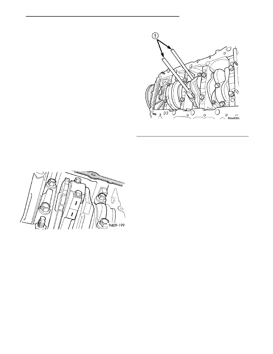
(3) Remove connecting rod cap. Install Special Tool

8189 Connecting Rod Guides into the connecting rod
being removed (Fig. 70). Remove each piston and rod
assembly out of cylinder bore.

NOTE: Be careful not to nick crankshaft journals.

(4) After removal, install bearing cap on the mat-

ing rod to prevent damage to the fractured cap to rod
surfaces.

INSTALLATION

(1) Install the piston rings. (Refer to 9 - ENGINE/

ENGINE

BLOCK/PISTON

RINGS

-

INSTALLA-

TION)

(2) Before installing piston and connecting rod

assemblies into the bore, ensure that compression
ring gaps are staggered so that neither is in line with
oil ring rail gap.

(3) Before installing the ring compressor, make

sure the oil ring expander ends are butted and the
rail gaps located as shown in (Fig. 78).

(4) Immerse the piston head and rings in clean

engine oil, slide the ring compressor over the piston
and tighten with the special wrench. Ensure posi-
tion of rings does not change during this oper-
ation.

CAUTION: Ensure the hole in bearing half aligns
with hole in connecting rod, as damage to engine
may occur.

(5) Position bearing onto connecting rod. Ensure

that hole in bearing half is aligned to hole in con-
necting rod. Lubricate bearing surface with clean
engine oil.

(6) Install Special Tools 8189 Connecting Rod

Guides into connecting rod (Fig. 70).

(7) The pistons are marked on top with an arrow

and with an “F” (Front) above the pin boss. These
marks must be pointing toward the front of engine
on both cylinder banks. The connecting rod oil squirt
hole faces the major thrust (right) side of the block
(Fig. 72).

(8) Rotate crankshaft so that the connecting rod

journal is on the center of the cylinder bore. Insert

Fig. 69 Identify Connecting Rod to Cylinder

Fig. 70 Connecting Rod Guides

1 - SPECIAL TOOL 8189 CONNECTING ROD GUIDES

JR

ENGINE 2.7L DOHC

9 - 203

PISTON & CONNECTING ROD (Continued)

rod and piston into cylinder bore and guide rod over
the crankshaft journal (Fig. 71).

CAUTION: Do Not interchange piston assemblies
bank to bank, as engine damage may occur.

(9) Tap the piston down in cylinder bore, using a

hammer handle. At the same time, guide connecting
rod into position on connecting rod journal.

(10) Lubricate rod bolts and bearing surface with

engine oil. Install connecting rod cap and bearing.
Tighten bolts to 27 N·m (20 ft. lbs.) Plus 1/4 turn.

PISTON RINGS

STANDARD PROCEDURE - PISTON RING
FITTING

(1) Wipe cylinder bore clean. Insert ring and push

down with piston to ensure it is square in bore. The
ring gap measurement must be made with the ring
positioning at least 12 mm (0.50 inch.) from bottom
of cylinder bore. Check gap with feeler gauge (Fig.
73). Refer to (Refer to 9 - ENGINE - SPECIFICA-
TIONS) for clearance measurements.

(2) Check piston ring to groove clearance (Fig. 74).

For clearance specifications (Refer to 9 - ENGINE -
SPECIFICATIONS).

REMOVAL

(1) Remove piston and connecting rod. (Refer to 9 -

ENGINE/ENGINE BLOCK/PISTON & CONNECT-
ING ROD - REMOVAL)

(2) Remove No. 1 and No.2 piston rings (Fig. 76)

from piston using a ring expander tool (Fig. 77).

(3) Remove upper oil ring side rail (Fig. 76).
(4) Remove lower oil ring side rail (Fig. 76).
(5) Remove oil ring expander (Fig. 76).

INSTALLATION

(1) Measure clearance of piston rings to the cylin-

der bore and piston. (Refer to 9 - ENGINE/ENGINE
BLOCK/PISTON

RINGS

-

STANDARD

PROCE-

DURE)

Fig. 71 Piston and Connecting Rod

1 - “F” TOWARD FRONT OF ENGINE
2 - RING COMPRESSOR
3 - SPECIAL TOOL 8189
4 - OIL SQUIRT HOLE

9 - 204

ENGINE 2.7L DOHC

JR

PISTON & CONNECTING ROD (Continued)

CAUTION: Install piston rings in the following
order:

• Oil ring expander.

• Upper oil ring side rail.

• Lower oil ring side rail.

Fig. 72 Piston and Connecting Rod Positioning (Front View of Engine)

1 - MAJOR THRUST SIDE OF PISTON

2 - OIL SQUIRT HOLE

Fig. 73 CHECK GAP ON PISTON RINGS

1 - FEELER GUAGE

Fig. 74 Measuring Piston Ring Side Clearance

1 - FEELER GAUGE

JR

ENGINE 2.7L DOHC

9 - 205

PISTON RINGS (Continued)

• No. 2 Intermediate piston ring.

• No. 1 Upper piston ring.
(2) Install oil ring expander.
Install the side rail by placing one end between the

piston ring groove and the oil ring expander. Hold
end firmly and press down the portion to be installed
until side rail is in position. Do not use a piston
ring expander during this step (Fig. 75).

(3) Install upper side rail first and then the lower

side rail.

NOTE: The No. 1 and No. 2 piston rings have a dif-
ferent cross section. Ensure No. 2 ring is installed
with

manufacturers

I.D.

mark

(dot)

facing

up,

towards top of the piston (Fig. 76)

(4) Install No. 2 piston ring and then No. 1 piston

ring (Fig. 77).

(5) Position piston ring end gaps as shown in (Fig.

78).

(6) Position oil ring expander gap at least 45° from

the side rail gaps but not on the piston pin center or
on the thrust direction. Staggering ring gap is impor-
tant for oil control.

Fig. 75 SIDE RAIL - INSTALLATION

1 - SIDE RAIL END

Fig. 76 PISTON RING - INSTALLATION

1 - SPACER EXPANDER
2 - SIDE RAIL

Fig. 77 UPPER AND INTERMEDIATE RINGS

Fig. 78 PISTON RING END GAP POSITION

1 - SIDE RAIL UPPER
2 - NO. 1 RING GAP
3 - PISTON PIN
4 - SIDE RAIL LOWER
5 - NO. 2 RING GAP AND SPACER EXPANDER GAP

9 - 206

ENGINE 2.7L DOHC

JR

PISTON RINGS (Continued)


Content   ..  523  524  525  526   ..