Chrysler Sebring, Stratus sedan, Sebring Convertible. Manual - part 524


  Index      Chrysler     Chrysler Sebring, Stratus sedan, Sebring Convertible - service repair manual 2001-2007 year


Search            


Content   ..  522  523  524  525   ..


Chrysler Sebring, Stratus sedan, Sebring Convertible. Manual - part 524


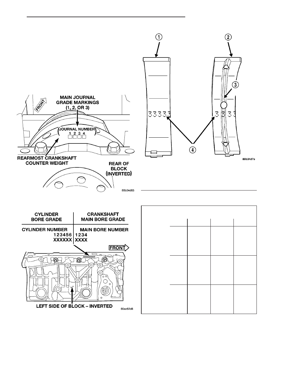
NOTE: Service main bearings have a number from
1–5 marked in ink on the bearing surface (Fig. 60).
For verification, use the MAIN BEARING SELEC-
TION CHART—2.7L for number to size identification.

The upper main bearing has a oil feed hole and a

center groove to allow lubrication of the main journal
and must be properly positioned in the block.

NOTE: Although cylinder bores are graded for size,
there is only one piston size.

MAIN BEARING SELECTION CHART—2.7L

Main Bearing Bore Grade

Mark

1

2

3

Crankshaft

Main

Journal

Grade

Mark

1

(3)

standard

(2)

+0.003

mm

(+0.0002

in.)

(1)

+0.006

mm

(+0.0003

in.)

2

(4)

-0.003

mm

(-

0.0002)

(3)

standard

(2)

+0.003

mm

(+0.0002

in.)

3

(5)

-0.006

mm

(-0.0003

in.)

(4)

-0.003

mm

(-0.0002

in.)

(3)

standard

Fig. 58 Crankshaft Main Journal Grade Marking

Location

Fig. 59 Cylinder Block Main Bore Grade Marking

Fig. 60 Main Bearing Grade Marks

1 - LOWER MAIN BEARING
2 - UPPER MAIN BEARING
3 - OIL FEED HOLE AND GROOVE
4 - GRADE SELECTION INK MARKS

JR

ENGINE 2.7L DOHC

9 - 199

CRANKSHAFT MAIN BEARINGS (Continued)

CRANKSHAFT OIL SEAL -
FRONT

REMOVAL

(1) Remove crankshaft vibration damper. (Refer to

9

-

ENGINE/ENGINE

BLOCK/VIBRATION

DAMPER - REMOVAL)

(2) Install Special Tool 8194, Insert into crankshaft

nose. Remove seal using Special Tool 6771, Remover
(Fig. 61).

INSTALLATION

(1) Install new seal using Special Tools 6780-2

Sleeve, 6780-1 Installer, and 8179 Stud (Fig. 62).

(2) Install crankshaft vibration damper. (Refer to 9

- ENGINE/ENGINE BLOCK/VIBRATION DAMPER -
INSTALLATION)

CRANKSHAFT OIL SEAL -
REAR

REMOVAL

(1) Remove transaxle from vehicle. (Refer to 21 -

TRANSMISSION/TRANSAXLE/AUTOMATIC - 42LE
- REMOVAL)

(2) Remove drive plate.
(3) Insert a 3/16” wide flat bladed screwdriver

between the dust lip and the metal case of the crank-
shaft seal. Angle the screwdriver (Fig. 63) through
the dust lip against the metal case of the seal. Pry
out seal.

CAUTION: Do not allow the screwdriver blade to
contact the crankshaft seal surface. Contact of the
screwdriver blade against crankshaft edge (cham-
fer) is permitted.

INSTALLATION

CAUTION: If a burr or scratch is present on the
crankshaft edge (chamfer), clean surface using 400
grit sand paper to prevent seal damage during
installation.

(1) Place Special Tool 6926-1 Guide on crankshaft

(Fig. 64). This is a pilot tool with a magnetic base.

(2) Position seal over pilot tool. Assure that lip of

seal is facing towards the crankshaft during installa-
tion. The pilot tool remains on crankshaft during seal
installation.

(3) Using Special Tool 6926-2 Installer, and C-4171

Handle (Fig. 64), drive seal into the retainer housing
until seal is flush with housing surface.

Fig. 61 Crankshaft Front Oil Seal - Removal

1 - SPECIAL TOOL 6771

Fig. 62 Crankshaft Front Oil Seal - Installation

1 - SPECIAL TOOL 6780–2
2 - SPECIAL TOOL 8179
3 - SPECIAL TOOL 6780–1
4 - SEAL

9 - 200

ENGINE 2.7L DOHC

JR

(4) Install drive plate and transaxle. (Refer to 21 -

TRANSMISSION/TRANSAXLE/AUTOMATIC - 42LE
- INSTALLATION)

CRANKSHAFT REAR OIL SEAL
RETAINER

REMOVAL

(1) Remove crankshaft rear oil seal and oil pan.

(Refer to 9 - ENGINE/ENGINE BLOCK/CRANK-
SHAFT OIL SEAL - REAR - REMOVAL) (Refer to 9 -
ENGINE/LUBRICATION/OIL PAN - REMOVAL)

(2) Remove seal retainer attaching screws (Fig.

65).

(3) Remove retainer and gasket (Fig. 65).

INSTALLATION

(1) Clean sealing surfaces and replace gasket as

needed.

(2) Install gasket and loose assemble seal retainer

to block.

NOTE: The following steps must be performed to
prevent oil leaks at sealing joints.

(3) Attach Special Tools 8225 to pan rail using the

oil pan fasteners.

NOTE: Make sure that the “2.7L” stamped on the
special tool is facing the cylinder block (flat side of
tools against pan rail).

Fig. 63 Rear Crankshaft Oil Seal Removal - Typical

1 - REAR CRANKSHAFT SEAL
2 - ENGINE BLOCK
3 - ENGINE BLOCK
4 - REAR CRANKSHAFT SEAL METAL CASE
5 - PRY IN THIS DIRECTION
6 - CRANKSHAFT
7 - SCREWDRIVER
8 - REAR CRANKSHAFT SEAL DUST LIP
9 - SCREWDRIVER

Fig. 64 Crankshaft Rear Seal - Installation

1 - C-4171 HANDLE
2 - 6926–2 INSTALLER
3 - 6926–1 GUIDE
4 - SEAL

Fig. 65 Oil Seal Retainer

1 - SCREWS (7)
2 - SEAL RETAINER

JR

ENGINE 2.7L DOHC

9 - 201

CRANKSHAFT OIL SEAL - REAR (Continued)

(4) While applying firm pressure to the seal

retainer against Special Tools 8225 (Fig. 66), tighten
seal retainer screws to 12 N·m (105 in. lbs.).

(5) Install oil pan and crankshaft rear oil seal.

(Refer to 9 - ENGINE/LUBRICATION/OIL PAN -
INSTALLATION) (Refer to 9 - ENGINE/ENGINE
BLOCK/CRANKSHAFT

OIL

SEAL

-

REAR

-

INSTALLATION)

PISTON & CONNECTING ROD

DESCRIPTION

The pistons are made of a high strength aluminum

alloy with an anodized top ring groove. Piston skirts
are coated with a solid lubricant for scuff resistance.
The connecting rods are made of powdered metal
with a “fractured cap” design. The connecting rod
attaches to the piston with a full floating pin
retained by lock rings. The piston and connecting rod
are serviced as an assembly (Fig. 67).

STANDARD PROCEDURE - FITTING PISTONS

The pistons have been cast and machined to one

size and weight. The piston and rod assemblies are
matched to weigh the same for engine balance.

Piston and cylinder wall must be clean and dry.

Piston diameter should be measured 90 degrees to
piston pin at size location shown in (Fig. 68). Cylin-
der bores should be measured halfway down the cyl-
inder bore and transverse to the engine crankshaft
center line. Refer to Engine Specifications. (Refer to 9
- ENGINE - SPECIFICATIONS) Pistons and cylin-
der bores should be measured at normal room
temperature, 70°F (21°C).

PISTON PINS

The pistons have been cast and machined to one

size and weight. The piston and rod assemblies are
matched to weigh the same for engine balance.

The piston pin is full floating and is held in place

by lock rings. Do Not switch pistons with other

Fig. 66 Seal Retainer Alignment - Typical

1 - SPECIAL TOOLS 8225
2 - SEAL RETAINER

Fig. 67 Piston and Connecting Rod

1 - “F” TOWARD FRONT OF ENGINE
2 - RING COMPRESSOR
3 - SPECIAL TOOL 8189
4 - OIL SQUIRT HOLE

Fig. 68 Piston Measurements

9 - 202

ENGINE 2.7L DOHC

JR

CRANKSHAFT REAR OIL SEAL RETAINER (Continued)


Content   ..  522  523  524  525   ..