Chrysler Sebring, Stratus sedan, Sebring Convertible. Manual - part 521


  Index      Chrysler     Chrysler Sebring, Stratus sedan, Sebring Convertible - service repair manual 2001-2007 year


Search            


Content   ..  519  520  521  522   ..


Chrysler Sebring, Stratus sedan, Sebring Convertible. Manual - part 521


VALVE SPRINGS

DESCRIPTION

The valve springs are made from high strength,

chrome-silicon steel (Fig. 15). The springs are com-
mon for intake and exhaust applications. The valve
spring seat is integral with the valve stem seal,
which incorporates a garter spring to maintain con-
sistent lubrication control to the valve stem.

REMOVAL

REMOVAL - IN VEHICLE

(1) Perform fuel system pressure release procedure

before attempting any repairs. (Refer to 14 -
FUEL SYSTEM/FUEL DELIVERY - STANDARD
PROCEDURE)

(2) Disconnect negative cable from remote jumper

terminal.

(3) Remove air cleaner housing and inlet hose.

(4) Remove upper intake manifold. (Refer to 9 -

ENGINE/MANIFOLDS/INTAKE

MANIFOLD

-

REMOVAL)

(5) Remove cylinder head covers. (Refer to 9 -

ENGINE/CYLINDER

HEAD/CYLINDER

HEAD

COVER(S) - REMOVAL)

(6) Remove crankshaft vibration damper (Refer to

9

-

ENGINE/ENGINE

BLOCK/VIBRATION

DAMPER - REMOVAL), timing chain cover (Refer to
9

-

ENGINE/VALVE

TIMING/TIMING

BELT

/

CHAIN COVER(S) - REMOVAL), and timing chain
(Refer to 9 - ENGINE/VALVE TIMING/TIMING
BELT/CHAIN AND SPROCKETS - REMOVAL).

(7) Remove camshafts and rocker arms. (Refer to 9

-

ENGINE/CYLINDER

HEAD/CAMSHAFT(S)

-

REMOVAL)

(8) With air hose attached to spark plug adapter

installed in the cylinder being serviced, apply 620.5–
689 kPa (90–100 psi) air pressure. This is to hold
valves in place while servicing components.

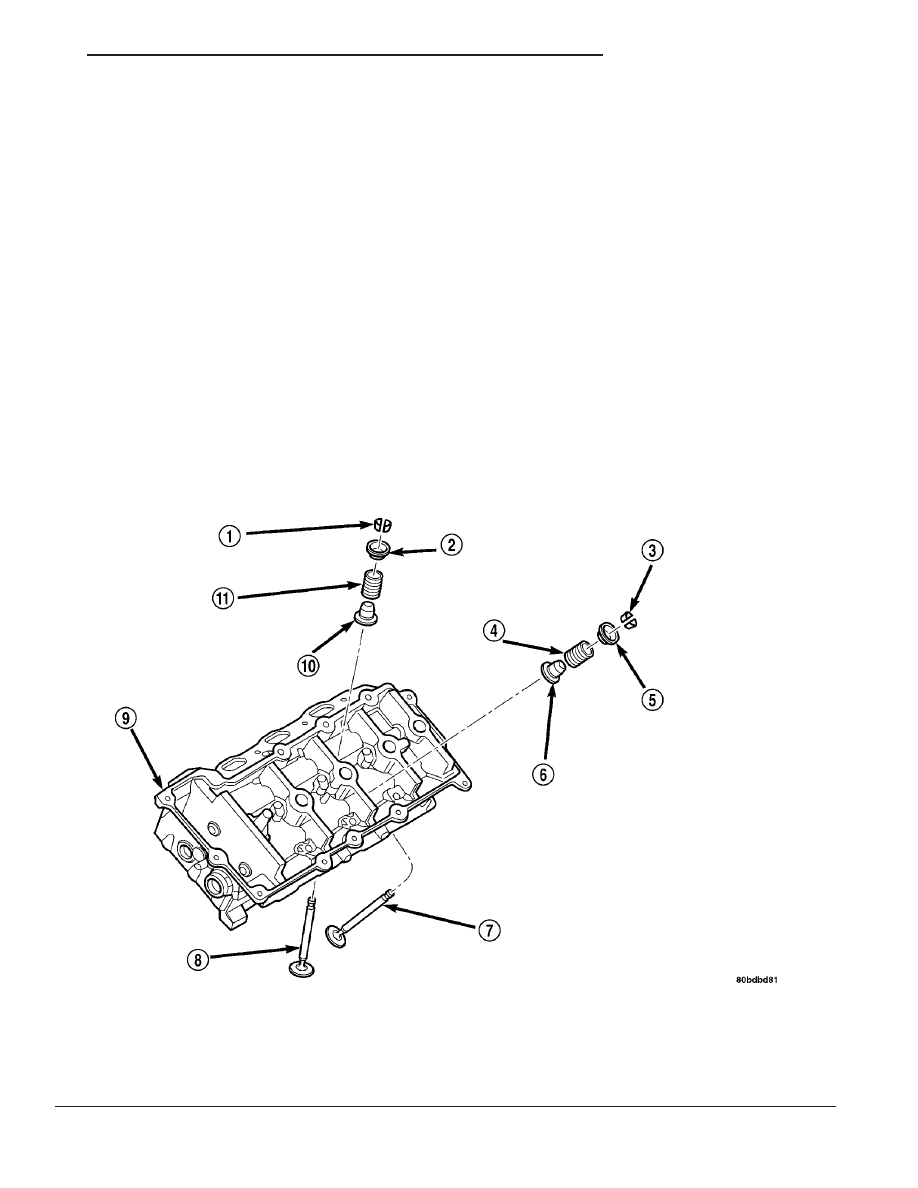
Fig. 38 VALVE, SPRING SEAT/SEAL, SPRING, REATINER AND LOCKS

1 - VALVE KEEPER

7 - VALVE-EXHAUST

2 - SPRING RETAINER

8 - VALVE-INTAKE

3 - VALVE KEEPER

9 - CYLINDER HEAD

4 - VALVE SPRING-EXHAUST

10 - VALVE STEM SEAL

5 - SPRING RETAINER

11 - VALVE SPRING-INTAKE

6 - VALVE STEM SEAL

JR

ENGINE 2.7L DOHC

9 - 187

(9) Using Special Tool MD 998772A with adapter

6779, compress valve spring and remove valve locks,
retainer, and valve spring.

(10) Remove

valve

stem

seal

(Refer

to

9

-

ENGINE/CYLINDER HEAD/VALVE STEM SEALS -
REMOVAL).

REMOVAL - OFF VEHICLE

(1) With cylinder head removed, compress valve

springs using a Special Tool C-3422-D, Valve Spring
Compressor.

(2) Remove valve retaining locks, valve spring

retainers, valve springs and valve spring seat/stem
seal assembly (Fig. 38).

INSPECTION

Whenever valves have been removed for inspection,

reconditioning or replacement, valve springs should
be tested (Fig. 39). As an example; the compression
length of a spring to be tested is 38.00 mm (1.496
in.). Turn the table of Tool C-647 until surface is in
line with the 38.00 mm (1.496 in.) mark on the
threaded stud and the zero mark on the front. Place
spring over stud on the table and lift compressing
lever to set tone device. Pull on torque wrench until
ping is heard. Take reading on torque wrench at this
instant. Multiply this reading by two. This will give
the spring load at test length. Fractional measure-
ments are indicated on the table for finer adjust-
ments. Refer to Engine Specifications to obtain
specified height and allowable tensions (Refer to 9 -
ENGINE - SPECIFICATIONS). Replace any springs
that do not meet specifications.

INSTALLATION

INSTALLATION - IN VEHICLE

(1) The valve stem seal/valve spring seat should be

pushed firmly and squarely over the valve guide
using the valve stem as guide. Do Not Force seal
against top of guide. When installing the valve
retainer locks, compress the spring only enough to
install locks

(2) Follow the same procedure on the remaining

cylinders using the firing sequence 1-2-3-4-5-6. Make
sure piston is at TDC on the cylinder that the
valve spring is to be removed.

(3) Remove spark plug adapter tool and Special

Tool MD 998772A.

(4) Install rocker arm(s).
(5) Install camshafts (Refer to 9 - ENGINE/CYL-

INDER HEAD/CAMSHAFT(S) - INSTALLATION),
timing chain (Refer to 9 - ENGINE/VALVE TIMING/
TIMING

BELT/CHAIN

AND

SPROCKETS

-

INSTALLATION), and timing chain cover (Refer to 9
- ENGINE/VALVE TIMING/TIMING BELT / CHAIN
COVER(S) - INSTALLATION).

(6) Install cylinder head covers. (Refer to 9 -

ENGINE/CYLINDER

HEAD/CYLINDER

HEAD

COVER(S) - INSTALLATION)

(7) Install upper intake manifold. (Refer to 9 -

ENGINE/MANIFOLDS/INTAKE

MANIFOLD

-

INSTALLATION)

(8) Install air cleaner housing and inlet hose.
(9) Connect negative cable.

Fig. 39 TESTING VALVE SPRING

1 - SPECIAL TOOL C-647

9 - 188

ENGINE 2.7L DOHC

JR

VALVE SPRINGS (Continued)

INSTALLATION - OFF VEHICLE

(1) If removed, install valve(s). (Refer to 9 -

ENGINE/CYLINDER

HEAD/INTAKE/EXHAUST

VALVES & SEATS - INSTALLATION)

(2) If valves or seats have been reground, check

valve tip height (A) (Fig. 40). If valve tip height for
intake valve is greater than 47.59 mm (1.8737 in.) or
49.14 mm (1.9347 in.) for exhaust valve, grind valve
tip until within specifications. Make sure measure-
ment is taken from cylinder head surface to the top
of valve stem.

(3) Install valve seal/spring seat assembly over

valve guides on all valve stems (Fig. 41). Ensure that
the garter spring is intact around the top of the rub-
ber seal. Install valve springs, valve retainers.

(4) Compress valve springs with a valve spring

compressor install locks and release tool. If valves
and/or

seats

are

reground,

measure

the

installed height of springs (B) (Fig. 40), make
sure measurements are taken from top of
spring seat to the bottom surface of spring
retainer. 
If height is greater than 38.75 mm (1.5256
in.), install a 0.762 mm (0.030 in.) spacer in head
counterbore under the valve spring seat to bring
spring height back within specification.

VALVE STEM SEALS

REMOVAL

(1) Remove valve spring. (Refer to 9 - ENGINE/

CYLINDER HEAD/VALVE SPRINGS - REMOVAL)

(2) Remove valve stem seal by using a valve seal

tool (Fig. 42).

Fig. 40 Valve Tip Height and Valve Spring Installed

Height

1 - SPRING RETAINER
2 - GARTER SPRING
3 - VALVE SPRING SEAT TOP
4 - CYLINDER HEAD SURFACE

Fig. 41 Valve Seal and Spring

1 - VALVE RETAINING LOCKS
2 - VALVE SPRING RETAINER
3 - VALVE SPRING
4 - VALVE SEAL AND VALVE SPRING SEAT ASSEMBLY
5 - VALVE

Fig. 42 Valve Stem Seal—Removal

1 - VALVE SEAL TOOL
2 - VALVE STEM

JR

ENGINE 2.7L DOHC

9 - 189

VALVE SPRINGS (Continued)

INSTALLATION

(1) The valve stem seal/valve spring seat should be

pushed firmly and squarely over the valve guide
using the valve stem as guide. Do Not Force seal
against top of guide.

(2) Install valve spring. (Refer to 9 - ENGINE/

CYLINDER HEAD/VALVE SPRINGS - INSTALLA-
TION)

HYDRAULIC LASH
ADJUSTERS

DIAGNOSIS AND TESTING - HYDRAULIC LASH
ADJUSTER NOISE DIAGNOSIS

Proper noise diagnosis is essential in locating the

source of a NVH complaint. Locating a lash adjuster

(tappet) type noise can sometimes be difficult. As a
result, an initial misdiagnosis may occur.

Refer to LASH ADJUSTER (TAPPET) NOISE

CHART indicating possible lash adjuster (tappet)
noise sources and possible sources that could lead to
a misdiagnosis.

Refer to LASH ADJUSTER (TAPPET) NOISE

CHART for possible causes and correction of a lash
adjuster (tappet) type noise.

LASH ADJUSTER (TAPPET) NOISE CHART

POSSIBLE CAUSES

CORRECTION

1. Engine oil level—too high or too low. This may cause
aerated oil to enter the adjusters and cause them to be
spongy.

1. Check and correct engine oil level.

2. Insufficient running time after rebuilding cylinder
head.

2. Low speed running of up to 1 hour may be required
to fully evacuate trapped air from the valve train
system. During this time, turn engine off and let set for
a few minutes before restarting. Repeat this several
times after engine has reached normal operating
temperature.

3. Air trapped in lash adjuster (after 1 hour run time).

3. See below:

(a) Check lash adjusters for sponginess while installed
in cylinder head. Depress part of rocker arm over
adjuster. Normal adjusters should feel very firm. Very
spongy adjusters can be bottomed out easily.

(b) If lash adjuster(s) are still spongy, replace with new
adjuster/rocker arm assembly.

4. Low oil pressure

4. See below:

(a) Check and correct engine oil level.

(b) Check engine oil pressure.

(c) Check for excessive bearing clearance and correct.

(d) Check for worn oil pump.

5. Oil passage to cylinder head(s) plugged with debris.

5. Check cylinder head oil passages and cylinder head
gasket restrictor for blockage. Clean or replace as
necessary.

9 - 190

ENGINE 2.7L DOHC

JR

VALVE STEM SEALS (Continued)


Content   ..  519  520  521  522   ..