Chrysler Sebring, Stratus sedan, Sebring Convertible. Manual - part 519


  Index      Chrysler     Chrysler Sebring, Stratus sedan, Sebring Convertible - service repair manual 2001-2007 year


Search            


Content   ..  517  518  519  520   ..


Chrysler Sebring, Stratus sedan, Sebring Convertible. Manual - part 519


(25) Remove cylinder head(s).
(26) Remove and discard cylinder head gasket.
(27) Clean cylinder head and block sealing sur-

faces. (Refer to 9 - ENGINE/CYLINDER HEAD -
CLEANING)

CLEANING

To ensure engine gasket sealing, proper surface

preparation must be performed, especially with the
use of aluminum engine components and multi-layer
steel cylinder head gaskets.

NOTE: Multi-Layer Steel (MLS) head gaskets require
a scratch free sealing surface.

Remove all gasket material from cylinder head and

block (Refer to 9 - ENGINE - STANDARD PROCE-
DURE). Be careful not to gouge or scratch the alumi-
num head sealing surface.

Clean all engine oil passages.

INSPECTION

(1) Before cleaning, check for leaks, damage and

cracks.

(2) Clean cylinder head and oil passages.
(3) Check cylinder head for flatness (Fig. 21).
(4) Cylinder head must be flat within:
• Standard dimension = less than 0.05 mm (0.002

inch.)

• Service Limit = 0.2 mm (0.008 inch.)

• Grinding Limit = Maximum of 0.2 mm (0.008

inch.) is permitted.

CAUTION: 0.20 mm (0.008 in.) MAX is a combined
total dimension of the stock removal limit from cyl-
inder head and block top surface (Deck) together.

INSTALLATION

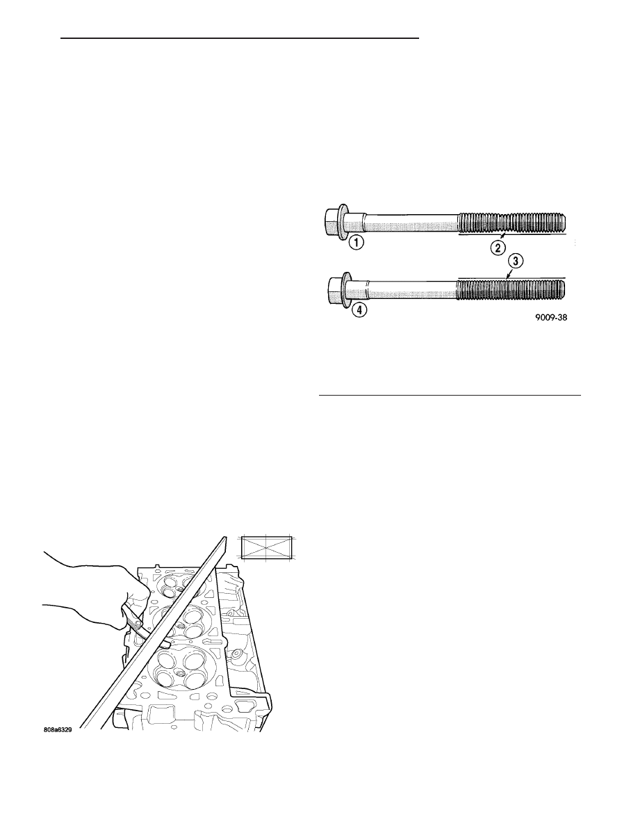
NOTE: The cylinder head bolts are tightened using
a torque plus angle procedure. The bolts must be
examined BEFORE reuse. If the threads are necked
down the bolts must be replaced (Fig. 22)

Necking can be checked by holding a straight edge

against the threads. If all the threads do not contact
the scale, the bolt must be replaced (Fig. 22)

CAUTION: When cleaning cylinder head and cylin-
der block surfaces, DO NOT use a metal scraper
because the surfaces could be cut or ground. Use
ONLY a wooden or plastic scraper.

(1) Clean sealing surfaces of cylinder head and

block (Refer to 9 - ENGINE - STANDARD PROCE-
DURE).

(2) Install new head gasket over locating dowels.
(3) Install cylinder head to block, assuring head is

properly positioned over locating dowels.

(4) Lubricate bolt threads with clean engine oil

and install bolts.

(5) Tighten bolts in sequence shown in (Fig. 23),

using the following steps and torque values:

• Step 1: Bolts 1–8 to 48 N·m (35 ft. lbs.)

• Step 2: Bolts 1–8 to 75 N·m (55 ft. lbs.)

• Step 3: Bolts 1–8 to 75 N·m (55 ft. lbs.)

• Step 4: Bolts 1–8 to +90° Turn Do not use a

torque wrench for this step.

• Step 5: Bolts 9–11 to 28 N·m (250 in. lbs.)
(6) For left cylinder head installation:
• Install engine oil dipstick tube.

• Install generator.
(7) For right cylinder head removal:
• Install cylinder head ground strap.

• Connect EGR valve electrical connector (if

equipped).

(8) Install all valvetrain components and cam-

shafts (Refer to 9 - ENGINE/CYLINDER HEAD/

Fig. 21 Checking Cylinder Head Flatness—Typical

Fig. 22 Check for Stretched Bolts

1 - STRETCHED BOLT
2 - THREADS ARE NOT STRAIGHT ON LINE
3 - THREADS ARE STRAIGHT ON LINE
4 - UNSTRETCHED BOLT

JR

ENGINE 2.7L DOHC

9 - 179

CYLINDER HEAD (Continued)

CAMSHAFT(S) - INSTALLATION). Tighten camshaft
bearing caps in sequence shown in (Fig. 24) to 12
N·m (105 in. lbs.).

(9) Install

primary

timing

chain,

guides

and

sprockets (Refer to 9 - ENGINE/VALVE TIMING/
TIMING CHAIN AND SPROCKETS - INSTALLA-
TION).

(10) Install coolant outlet connector (Refer to 7 -

COOLING/ENGINE/COOLANT OUTLET HOUSING
- INSTALLATION).

(11) Install cylinder head covers (Refer to 9 -

ENGINE/CYLINDER

HEAD/CYLINDER

HEAD

COVER(S) - INSTALLATION).

(12) Connect camshaft position sensor and crank-

shaft position sensor connectors.

(13) Install timing chain cover (Refer to 9 -

ENGINE/VALVE

TIMING/TIMING

CHAIN

COV-

ER(S) - INSTALLATION).

(14) Install crankshaft vibration damper (Refer to

9

-

ENGINE/ENGINE

BLOCK/VIBRATION

DAMPER - INSTALLATION).

(15) Install lower and upper intake manifolds

(Refer to 9 - ENGINE/MANIFOLDS/INTAKE MANI-
FOLD - INSTALLATION).

(16) Connect oil pressure sensor connector. Install

oil pressure sensor heat shield.

(17) Install catalytic converter(s) (Refer to 11 -

EXHAUST SYSTEM/CATALYTIC CONVERTER -
INSTALLATION).

(18) Install exhaust cross-under pipe (Refer to 11 -

EXHAUST SYSTEM/CROSS-OVER PIPE - INSTAL-
LATION).

(19) Install accessory drive belts (Refer to 7 -

COOLING/ACCESSORY

DRIVE/DRIVE

BELTS

-

INSTALLATION).

(20) Fill cooling system (Refer to 7 - COOLING/

ENGINE - STANDARD PROCEDURE).

(21) Connect negative cable to remote jumper ter-

minal.

CAMSHAFT(S)

DESCRIPTION

The assembled fabricated camshafts are composed

of five bearing journals machined into a hollow steel
tube (Fig. 25). Six steel lobes, a secondary timing
drive sprocket, and a primary sprocket/thrust flange
are pressed onto the camshaft tube using a unique
assembly process. Camshaft end play is controlled by
the primary camshaft sprocket attachment flange on
the intake camshafts and by a thrust flange on the
exhaust camshafts.

OPERATION

The camshaft has precisely machined (egg shaped)

lobes to provide accurate valve timing and duration.
The camshaft is driven by the crankshaft via drive
sprockets and chains.

REMOVAL

(1) Remove the primary timing chain. (Refer to 9 -

ENGINE/VALVE

TIMING/TIMING

BELT/CHAIN

AND SPROCKETS - REMOVAL)

(2) Remove secondary chain tensioner mounting

bolts.

NOTE: Camshaft bearing caps have been marked
during engine manufacturing. For example, number
one exhaust camshaft bearing is marked “1E>”

(3) Slowly loosen camshaft bearing cap bolts in

reverse order of installation (Fig. 26).

(4) Remove camshaft bearing caps.
(5) Remove camshafts, secondary chain, and ten-

sioner together as an assembly.

(6) Remove tensioner and camshaft chain from

camshafts.

Fig. 23 Cylinder Head Tightening Sequence

Fig. 24 Camshaft Bearing Cap Tightening Sequence

9 - 180

ENGINE 2.7L DOHC

JR

CYLINDER HEAD (Continued)

(7) Inspect camshafts. (Refer to 9 - ENGINE/CYL-

INDER HEAD/CAMSHAFT(S) - INSPECTION)

INSPECTION

(1) Inspect camshaft bearing journals for damage

and binding (Fig. 27). If journals are binding, check
the cylinder head for damage. Also check cylinder
head oil holes for clogging.

(2) Inspect camshaft sprockets for excessive wear.

Replace camshafts if necessary.

(3) Check the cam lobe surfaces for abnormal wear

and damage. Replace camshaft if defective. Measure
the actual wear (Fig. 27)and replace, if out of lim-
its—standard value is 0.0254 mm (0.001 in.); wear
limit is 0.254 mm (0.010 in.).

INSTALLATION

CAUTION: When the timing chain is removed and
the cylinder heads are installed, DO NOT rotate the
camshafts or crankshaft without first locating the
proper crankshaft position. Failure to do so will
result in valve and/or piston damage.

(1) Assemble camshaft chain on the cams. Ensure

that plated links are facing toward the front. Align
the plated links to the dot on the camshaft sprockets
(Fig. 29).

(2) If camshaft chain tensioner is already in the

compressed and locked position, proceed to step (4).

(3) When the camshaft chain tensioner is removed,

it is necessary to compress and lock the tensioner
using the following procedures:

(a) Place tensioner into a soft jaw vise (Fig. 28).

Fig. 25 Camshaft and Valvetrain Components

1 – CAMSHAFT BEARING CAP - INTAKE

7 – CAMSHAFT (SECONDARY) CHAIN TENSIONER

2 – CAMSHAFT BEARING CAP - EXHAUST

8 – CYLINDER BLOCK

3 – CAMSHAFT - EXHAUST

9 – CYLINDER HEAD

4 – ROCKER ARM

10 – CAMSHAFT - INTAKE

5 – HYDRAULIC LIFTER

11 – CAMSHAFT (SECONDARY) TIMING CHAIN

6 – CYLINDER HEAD

Fig. 26 Camshaft Bearing Cap Tightening Sequence

JR

ENGINE 2.7L DOHC

9 - 181

CAMSHAFT(S) (Continued)

(b) SLOWLY compress tensioner until fabricated

lock pin or the equivalent can be inserted into the
locking holes.

(c) Remove compressed and locked tensioner

from the vise.

(4) Insert the compressed and locked camshaft

chain tensioner in-between the camshafts and chain.

(5) Rotate the cams so that the plated links and

dots are facing the 12:00 O’clock position (Fig. 29).

(6) Install cams to cylinder head. Ensure that

rocker arms are correctly seated and in proper posi-
tions.

(7) Install camshaft bearing caps. Ensure that

bearing caps are installed in same position as
removed.

(8) Tighten cam bearing cap bolts gradually in

sequence shown in (Fig. 26) to 12 N·m (105 in. lbs.).

(9) Install secondary chain tensioner bolts and

tighten to 12 N·m (105 in. lbs.).

(10) Remove locking pin from secondary tension-

ers.

(11) Measure camshafts end play. (Refer to 9 -

ENGINE/CYLINDER HEAD/CAMSHAFT(S) - STAN-
DARD PROCEDURE)

(12) Install the primary timing chain. (Refer to 9 -

ENGINE/VALVE

TIMING/TIMING

BELT/CHAIN

AND SPROCKETS - INSTALLATION)

Fig. 27 Camshaft Inspection

1 - ACTUAL WEAR
2 - BEARING JOURNAL
3 - EXHAUST CAMSHAFT
4 - INTAKE CAMSHAFT
5 - LOBE

Fig. 28 Locking Camshaft (Secondary) Chain

Tensioner

1 - VISE
2 - LOCK PIN

Fig. 29 Camshaft Chain Timing

1 - PLATED CHAIN LINKS
2 - CAMSHAFT TIMING MARKS (DOTS)

9 - 182

ENGINE 2.7L DOHC

JR

CAMSHAFT(S) (Continued)


Content   ..  517  518  519  520   ..