Chrysler Sebring, Stratus sedan, Sebring Convertible. Manual - part 488


  Index      Chrysler     Chrysler Sebring, Stratus sedan, Sebring Convertible - service repair manual 2001-2007 year


Search            


Content   ..  486  487  488  489   ..


Chrysler Sebring, Stratus sedan, Sebring Convertible. Manual - part 488


LUBRICATION

DESCRIPTION

The lubrication system is a full-flow filtration,

pressure feed type. The oil pump (Fig. 81) is mounted
in the front engine cover and driven by the crank-
shaft.

OPERATION

Refer to (Fig. 82) for lubrication system flow.
Engine oil drawn from the oil pan sump through

the pickup tube is pressurized by the pump and
routed through the full-flow filter to the main oil gal-
lery running the length of the cylinder block. A diag-
onal hole in each bulkhead feeds oil to each main
bearing. Drilled passages within the crankshaft route
oil from main bearing journals to connecting rod jour-
nals. A vertical hole at the number five bulkhead
routes pressurized oil through a restrictor and up
past a cylinder head bolt to an oil gallery running

the length of the cylinder head. The restrictor, an
integral part of the cylinder head gasket, provides
increased oil flow to the main oil gallery. The cam-
shaft journals are partially slotted to allow a prede-
termined amount of pressurized oil to pass into the
bearing cap cavities with small holes directed to
spray lubricate the camshaft lobes. Oil returning to
the pan from pressurized components supplies lubri-
cation to the valve stems. Cylinder bores and wrist
pins are splash lubricated from directed slots on the
connecting rod thrust collars.

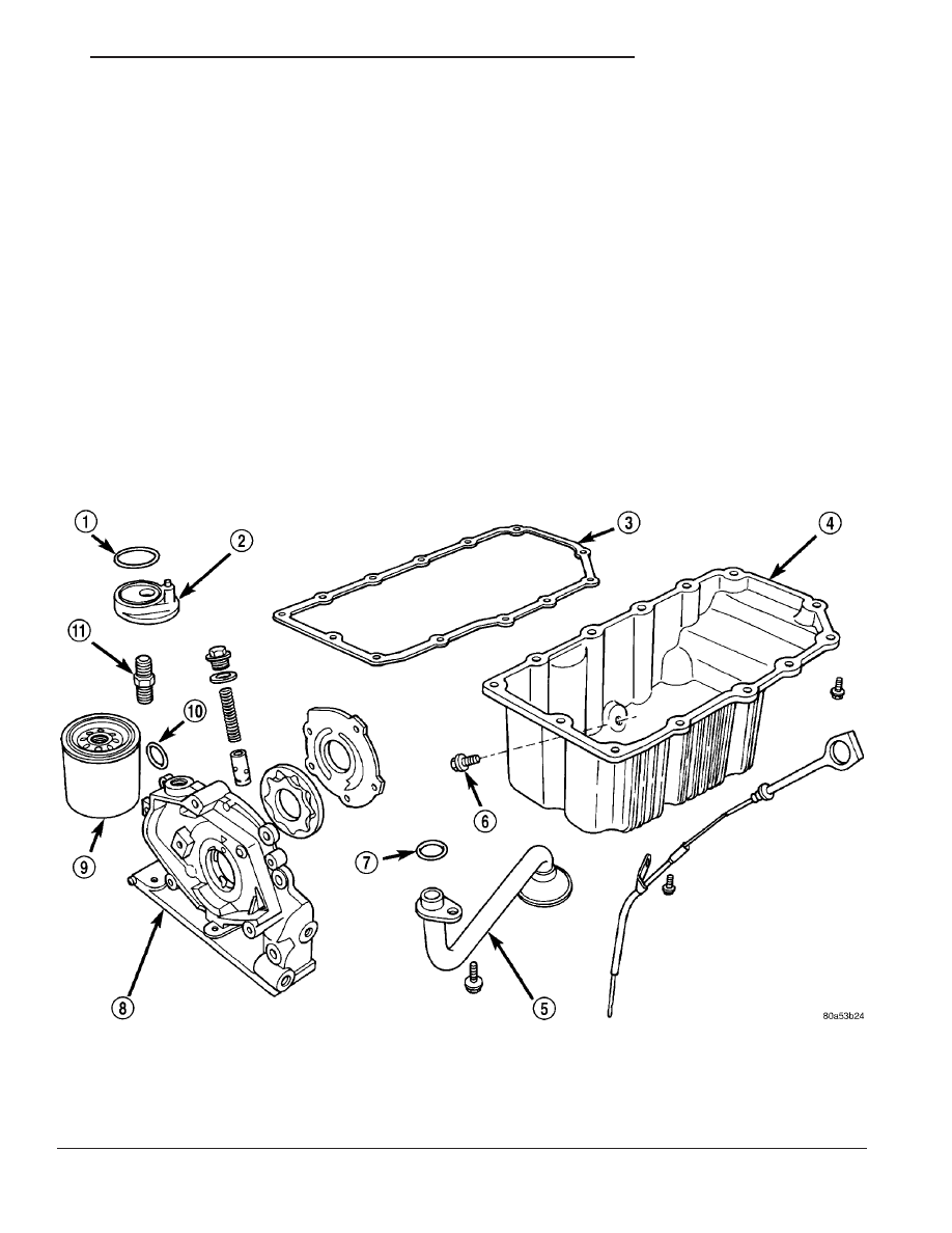
Fig. 81 Engine Lubrication Components

1 - O-RING

7 - O-RING

2 - OIL FILTER ADAPTER

8 - OIL PUMP BODY

3 - OIL PAN GASKET

9 - FILTER

4 - OIL PAN

10 - O-RING

5 - OIL PICK-UP TUBE

11 - NIPPLE

6 - DRAIN PLUG

JR

ENGINE 2.0L DOHC

9 - 55

DIAGNOSIS AND TESTING

CHECKING ENGINE OIL PRESSURE

Check oil pressure using a gauge at oil pressure

switch location.

(1) Remove oil pressure switch.
(2) Install oil pressure test gauge assembly C-3292

with adaptor 8406. For Special Tool identification,
(Refer to 9 - ENGINE - SPECIAL TOOLS).

CAUTION: If oil pressure is 0 at idle, Do Not Run
engine at 3000 RPM.

(3) Warm engine to normal operating temperature.
(4) Monitor gauge readings at idle and 3000 rpm.

Oil Pressure: Idle 25 kPa (4 psi) minimum, 3000
RPM 
170-550 kPa (25-80 psi).

(5) If oil pressure is 0 at idle, shut off engine and

check the following:

• Pressure relief valve stuck open

• Clogged oil pick-up screen

• Damaged oil pick-up tube O-ring

OIL

STANDARD PROCEDURE

ENGINE OIL LEVEL CHECK

The best time to check engine oil level is after it

has sat overnight, or if the engine has been running,
allow the engine to be shut off for at least 5 minutes
before checking oil level.

Checking the oil while the vehicle is on level

ground will improve the accuracy of the oil level
reading. Remove dipstick and observe oil level (Fig.
83). Add oil only when the level is at or below the
ADD mark (Fig. 84).

STANDARD PROCEDURE - ENGINE OIL AND
FILTER CHANGE

Change engine oil at mileage and time intervals

described in the Maintenance Schedule. (Refer to
LUBRICATION

&

MAINTENANCE/MAINTE-

NANCE SCHEDULES - DESCRIPTION)

WARNING: NEW OR USED ENGINE OIL CAN BE
IRRITATING TO THE SKIN. AVOID PROLONGED OR
REPEATED SKIN CONTACT WITH ENGINE OIL.
CONTAMINANTS IN USED ENGINE OIL, CAUSED BY
INTERNAL COMBUSTION, CAN BE HAZARDOUS TO
YOUR HEALTH. THOROUGHLY WASH EXPOSED
SKIN WITH SOAP AND WATER. DO NOT WASH
SKIN WITH GASOLINE, DIESEL FUEL, THINNER, OR
SOLVENTS, HEALTH PROBLEMS CAN RESULT. DO
NOT POLLUTE, DISPOSE OF USED ENGINE OIL
PROPERLY. CONTACT YOUR DEALER OR GOVERN-
MENT AGENCY FOR LOCATION OF COLLECTION
CENTER IN YOUR AREA.

Run engine until achieving normal operating tem-

perature.

(1) Position the vehicle on a level surface and turn

engine off.

(2) Remove oil fill cap.
(3) Raise vehicle on hoist.
(4) Place a suitable drain pan under crankcase

drain.

(5) Remove drain plug from crankcase and allow

oil to drain into pan. Inspect drain plug threads for
stretching or other damage. Replace drain plug and
gasket if damaged.

(6) Remove oil filter. (Refer to 9 - ENGINE/LUBRI-

CATION/OIL FILTER - REMOVAL)

(7) Install and tighten drain plug in crankcase.
(8) Install new oil filter. (Refer to 9 - ENGINE/LU-

BRICATION/OIL FILTER - INSTALLATION)

(9) Lower vehicle and fill crankcase with specified

type and amount of engine oil. (Refer to LUBRICA-

Fig. 82 Engine Lubrication System

1 - RESTRICTOR

9 - 56

ENGINE 2.0L DOHC

JR

LUBRICATION (Continued)

TION

&

MAINTENANCE/FLUID

TYPES

-

DESCRIPTION)

(10) Install oil fill cap.
(11) Start engine and inspect for leaks.
(12) Stop engine and inspect oil level.

NOTE: Care should be exercised when disposing
used engine oil after it has been drained from a
vehicle engine. Refer to the WARNING listed above.

OIL FILTER

REMOVAL

CAUTION: When servicing the oil filter (Fig. 85),
avoid deforming the filter. Use an appropriate oil fil-
ter removing tool. Position filter wrench strap close

the seam at the base of the filter. The oil filter seam
that joins the can to the base, is reinforced by the
base plate.

(1) Turn filter counterclockwise to remove (Fig.

85).

Fig. 83 Fluid Level Check - 2.0/2.4L

1 - COOLANT RECOVERY CONTAINER
2 - COOLANT PRESSURE CAP

3 - ENGINE OIL FILL
4 - ENGINE OIL DIPSTICK

Fig. 84 Oil Level

1 - ENGINE OIL LEVEL DIPSTICK

Fig. 85 Engine Oil Filter

1 - OIL FILTER
2 - DRAIN PLUG

JR

ENGINE 2.0L DOHC

9 - 57

OIL (Continued)

INSTALLATION

(1) Clean and check the filter mounting surface.

The surface must be smooth, flat and free of debris
or old pieces of rubber.

(2) Lubricate new filter gasket.
(3) Screw filter on until gasket contacts base (Fig.

85). Tighten to 11 N·m (8 ft. lbs.).

OIL FILTER ADAPTER

REMOVAL

(1) Remove the oil filter (Refer to 9 - ENGINE/LU-

BRICATION/OIL FILTER - REMOVAL).

(2) Remove assembly by unscrewing adaptor fit-

ting (Fig. 86).

(3) Remove O-ring seal.

INSTALLATION

(1) Position O-ring in the groove on adapter.
(2) Align roll pin into engine block and tighten

assembly to 80 N·m (60 ft. lbs.) (Fig. 86).

(3) Install oil filter (Refer to 9 - ENGINE/LUBRI-

CATION/OIL FILTER - INSTALLATION).

OIL PAN

REMOVAL

(1) Disconnect negative cable from battery.
(2) Raise vehicle on hoist.
(3) Drain engine oil and remove oil filter.
(4) Remove oil filter adaptor from engine block

(Fig. 86) (Refer to 9 - ENGINE/LUBRICATION/OIL
FILTER ADAPTER - REMOVAL).

(5) Remove structural collar (Fig. 87).
(6) Remove lateral bending brace.
(7) Remove transaxle dust cover.
(8) Remove oil pan bolts.
(9) Remove oil pan.

INSTALLATION

(1) Clean oil pan and all sealing surfaces.
(2) Apply Mopar

t Silicone Rubber Adhesive Seal-

ant at the oil pump to engine block parting line (Fig.
88).

(3) Position a new oil pan gasket onto pan.
(4) Install oil pan and tighten screws to 12 N·m

(105 in. lbs.).

(5) Install transaxle dust cover.
(6) Install lateral bending brace.
(7) Install structural collar (Fig. 87) (Refer to 9 -

ENGINE/ENGINE BLOCK/STRUCTURAL COVER -
INSTALLATION).

Fig. 86 Engine Oil Filter Adapter to Engine Block

1 - O-RING
2 - LOCATING ROLL PIN
3 - OIL FILTER ADAPTER

Fig. 87 Structural Collar

1 - OIL PAN
2 - STRUCTURAL COLLAR

Fig. 88 Oil Pan Sealing

1 - PLACE A 1/8 INCH BEAD OF SEALER AT THE PARTING LINE
OF THE OIL PUMP TO ENGINE BLOCK

9 - 58

ENGINE 2.0L DOHC

JR

OIL FILTER (Continued)


Content   ..  486  487  488  489   ..