Chrysler Sebring, Stratus sedan, Sebring Convertible. Manual - part 487


  Index      Chrysler     Chrysler Sebring, Stratus sedan, Sebring Convertible - service repair manual 2001-2007 year


Search            


Content   ..  485  486  487  488   ..


Chrysler Sebring, Stratus sedan, Sebring Convertible. Manual - part 487


INSTALLATION

CAUTION: The torque procedure for the structural
collar must be followed, as damage to oil pan or
collar could occur.

(1) Install the structural collar (Fig. 73) using the

following 3 step torque sequence:

• Step 1: Install the collar to oil pan bolts and

tighten to 3 N·m (30 in. lbs.).

• Step 2: Install collar to transaxle bolts and

tighten to 108 N·m (80 ft. lbs.).

• Step 3: Final torque the collar to oil pan bolts to

54 N·m (40 ft. lbs.).

(2) Lower vehicle.

VIBRATION DAMPER

REMOVAL

(1) Disconnect negative battery cable.
(2) Support engine under oil pan with wooden

block and floor jack.

(3) Remove three right side engine mount vertical

bolts to front engine bracket.

(4) Raise vehicle on hoist.
(5) Remove right front wheel and belt splash

shield.

(6) Support engine under oil pan with a wooden

block and screw jack (Fig. 74).

(7) Remove front and rear engine mount through

bolts.

(8) Slowly lower engine down with screw jack.
(9) Remove accessory drive belts (Refer to 7 -

COOLING/ACCESSORY

DRIVE/DRIVE

BELTS

-

REMOVAL).

(10) Remove crankshaft damper bolt.
(11) Remove

damper

using

Special

Tool

8454

Puller and Insert 6827–A (Fig. 75).

INSTALLATION

(1) Install crankshaft vibration damper using M12

1.75 x 150 mm bolt, washer, thrust bearing and nut
from Special Tool 6792 (Fig. 76).

(2) Install crankshaft vibration damper bolt and

tighten to 136 N·m (100 ft. lbs.).

(3) Install accessory drive belts (Refer to 7 -

COOLING/ACCESSORY

DRIVE/DRIVE

BELTS

-

INSTALLATION).

(4) Raise engine with screw jack enough to install

front and rear engine mount through bolts. Torque
fasteners to 61 N·m (45 ft. lbs.).

(5) Install belt splash shield and right front wheel.
(6) Lower vehicle.
(7) Support engine under oil pan with wooden

block and floor jack.

(8) Slowly raise engine with floor jack until engine

mount bracket aligns with right side engine mount.
Install three vertical bolts to front engine bracket.
Torque fasteners to 61 N·m (45 ft. lbs.).

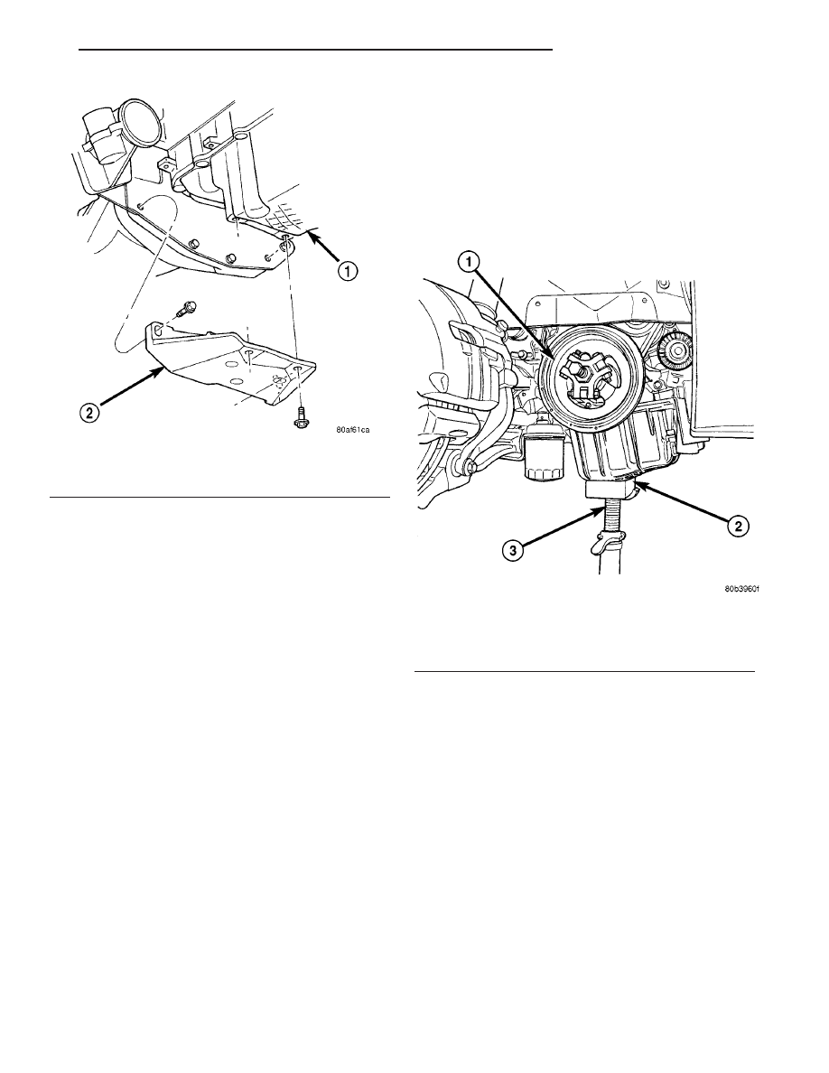
Fig. 73 Structural Collar - Removal/Installation

1 - OIL PAN
2 - STRUCTURAL COLLAR

Fig. 74 Vibration Damper - Removal

1 - VIBRATION DAMPER
2 - WOODEN BLOCK
3 - SCREW JACK

JR

ENGINE 2.0L DOHC

9 - 51

STRUCTURAL COLLAR (Continued)

(9) Remove floor jack.
(10) Connect negative battery cable.

ENGINE MOUNTING

ADJUSTMENTS

ENGINE SUPPORT ADJUSTMENT

The right and left support assemblies are slotted to

allow for right/left drive train adjustment in relation
to drive shaft assembly length.

Check and reposition right and left engine support

assemblies as required. Adjust drive train position, if
required, for the following conditions:

• Drive shaft distress: See Group 2, Suspension

and Driveshaft.

• Any front end structural damage (after repair).

• Support Assembly replacement.

ENGINE SUPPORT ADJUSTMENT

(1) Remove the load on the engine motor mounts

by carefully supporting the engine and transmission
assembly with a floor jack.

(2) Loosen the right engine support assembly ver-

tical fasteners.

(3) Loosen the left engine support assembly verti-

cal bolts.

(4) Pry the engine right or left as required to

achieve the proper drive shaft assembly length. Refer
to Group 2, Suspension and Driveshaft for driveshaft
identification and related assembly length measur-
ing.

(5) Tighten right engine support assembly vertical

bolts to 61 N·m (45 ft. lbs.). and tighten left engine
support assembly bolts to 61 N·m (45 ft. lbs.).

(6) Recheck drive shaft length.

LEFT MOUNT

REMOVAL

(1) Disconnect negative battery cable.
(2) Remove throttle body air inlet hose and air

cleaner housing assembly.

(3) Remove two nuts securing speed control servo

bracket to left shock tower. Reposition servo.

(4) Support

transmission

with

floor

jack

and

wooden block.

(5) Remove the three vertical bolts from mount to

transmission bracket (A) (Fig. 77).

(6) Slightly lower transmission with floor jack.
(7) Remove mount to frame rail fasteners (B) and

remove mount (Fig. 77).

INSTALLATION

(1) Position mount to frame rail. Install mount to

frame rail fasteners (B) (Fig. 77). Torque fasteners to
33 N·m (24 ft. lbs.).

Fig. 75 Vibration Damper - Removal

1 - SPECIAL TOOL 6827-A INSERT
2 - SPECIAL TOOL 8454 PULLER

Fig. 76 Vibration Damper - Installation

1 - M12–1.75 × 150 MM BOLT, WASHER AND THRUST BEARING
FROM SPECIAL TOOL 6792

9 - 52

ENGINE 2.0L DOHC

JR

VIBRATION DAMPER (Continued)

(2) Raise transmission into position with floor jack.
(3) Install three vertical bolts from mount to trans-

mission bracket (A) (Fig. 77). Torque fasteners to 61
N·m (45 ft. lbs.).

(4) Remove floor jack and wooden block.
(5) Install speed control servo to left shock tower.

Torque fasteners to 6.7 N·m (60 in. lbs.)

(6) Install throttle body air inlet hose and air

cleaner housing assembly.

(7) Connect negative battery cable.

RIGHT MOUNT

REMOVAL

(1) Remove coolant recovery container (Refer to 7 -

COOLING/ENGINE/COOLANT RECOVERY CON-
TAINER - REMOVAL).

(2) Remove heater tube front attaching screw.
(3) Raise vehicle on a hoist and remove inner

splash shield.

(4) Remove heater tube rear attaching screw.
(5) Remove the right engine support assembly ver-

tical fasteners from frame rail (Fig. 78).

(6) Lower vehicle. Remove the load on the engine

motor mounts by carefully supporting the engine
assembly with floor jack and wooden block on oil
pan.

(7) Remove the bolts attaching the engine support

assembly to the engine bracket (Fig. 78).

(8) Remove right engine mount.

INSTALLATION

(1) Position right engine mount and install frame

rail to mount bolts. Tighten bolts to 61 N·m (45 ft.
lbs.) (Fig. 78).

(2) Install the mount to engine support bracket

bolts and tighten to 61 N·m (45 ft. lbs.) (Fig. 78).

(3) Raise vehicle on a hoist.
(4) Install heater tube rear attaching screw.
(5) Install inner splash shield and lower vehicle.
(6) Install heater tube front attaching screw.
(7) Install coolant recovery container (Refer to 7 -

COOLING/ENGINE/COOLANT RECOVERY CON-
TAINER - INSTALLATION).

FRONT MOUNT

REMOVAL

(1) Raise vehicle.
(2) Remove front mount to bracket horizontal

through bolt (Fig. 79).

(3) Loosen rear mount through bolt.
(4) Remove front mount vertical bolts (Fig. 79).
(5) Remove front mount.

INSTALLATION

(1) Position front mount on lower radiator cross-

member.

(2) Loose install front mount to bracket through

bolt.

(3) Install front mount vertical bolts. Tighten bolts

to 61 N·m (45 ft. lbs.) (Fig. 79).

Fig. 77 Left Side Mount - Typical

1 - TRANSMISSION SUPPORT ASSEMBLY
2 - LEFT FRAME RAIL
3 - GROUND CABLE
4 - BOLT (D)
5 - TRANSMISSION BRACKET
6 - TRANSMISSION
7 - BOLT (C)
8 - BOLT (B)
9 - BOLT (A)

Fig. 78 Engine Mounting—Right Side

1 - ENGINE SUPPORT BRACKET
2 - FRAME RAIL
3 - RIGHT ENGINE MOUNT

JR

ENGINE 2.0L DOHC

9 - 53

LEFT MOUNT (Continued)

NOTE: Be sure the weight of the engine is static
and in rest position.

(4) Tighten the rear horizontal through bolt to 75

N·m (55 ft. lbs.) (Fig. 80)

(5) Tighten the front horizontal through bolt to 75

N·m (55 ft. lbs.) (Fig. 79).

(6) Lower vehicle.

REAR MOUNT

REMOVAL

(1) Remove throttle body air inlet hose and air

cleaner housing assembly.

(2) Remove three vertical bolts attaching rear

mount bracket to transaxle case (Fig. 80).

(3) Raise vehicle on hoist.
(4) Remove rear mount bracket through bolt (Fig.

80).

(5) Remove horizontal bolt attaching rear mount

bracket to transaxle case (Fig. 80).

(6) Loosen front mount though bolt.
(7) Remove mount bracket.
(8) Remove rear mount to suspension crossmember

attaching bolts.

(9) Remove rear mount.

INSTALLATION

(1) Position rear mount on suspension crossmem-

ber and loosely install bolts.

(2) Position mount bracket on transaxle and install

bolts. Tighten to 95 N·m (70 ft. lbs.) (Fig. 80).

(3) Tighten rear mount to crossmember bolts to 61

N·m (45 ft. lbs.) (Fig. 80)

NOTE: Be sure the weight of the engine is static
and in rest position.

(4) Install rear mount to bracket through bolt and

tighten rear mount through bolt to 75 N·m (55 ft.
lbs.) (Fig. 80).

(5) Tighten front mount through bolt to 75 N·m

(55 ft. lbs.) (Fig. 79)

(6) Lower vehicle. Install throttle body air inlet

hose and air cleaner housing assembly.

Fig. 79 FRONT ENGINE MOUNT

1 - HORIZONTAL THROUGH BOLT
2 - VERTICAL BOLT(S)
3 - LOWER RADIATOR CROSSMEMBER
4 - FRONT ENGINE MOUNT

Fig. 80 Engine Mounting—Rear

1 - REAR TORQUE BRACKET
2 - REAR MOUNT
3 - THROUGH BOLT

9 - 54

ENGINE 2.0L DOHC

JR

FRONT MOUNT (Continued)


Content   ..  485  486  487  488   ..