Chrysler Sebring, Stratus sedan, Sebring Convertible. Manual - part 485


  Index      Chrysler     Chrysler Sebring, Stratus sedan, Sebring Convertible - service repair manual 2001-2007 year


Search            


Content   ..  483  484  485  486   ..


Chrysler Sebring, Stratus sedan, Sebring Convertible. Manual - part 485


(19) Install each bolt finger tight then alternately

torque each bolt to assemble the cap properly.

(20) Tighten the connecting rod bolts using the 2

step torque-turn method. Tighten according to the
following values:

CAUTION: Do not use a torque wrench for the sec-
ond step.

1. Tighten the bolts to 27 N·m (20 ft. lbs.).
2. Tighten the connecting rod bolts an additional

1/4 TURN.

(21) Install oil pump (Refer to 9 - ENGINE/LU-

BRICATION/OIL PUMP - INSTALLATION).

(22) Install oil pump pick-up tube. Torque fastener

to 23 N·m (200 in. lbs.).

(23) Install the oil pan (Refer to 9 - ENGINE/LU-

BRICATION/OIL PAN - INSTALLATION).

(24) Install oil filter adapter and oil filter (Fig. 42)

(Refer to 9 - ENGINE/LUBRICATION/OIL FILTER
ADAPTER - INSTALLATION).

(25) Install rear timing belt cover and camshaft

sprockets (Refer to 9 - ENGINE/VALVE TIMING/
TIMING BELT COVER(S) - INSTALLATION).

(26) Install front crankshaft oil seal and crank-

shaft sprocket (Refer to 9 - ENGINE/ENGINE
BLOCK/CRANKSHAFT

OIL

SEAL

-

FRONT

-

INSTALLATION).

(27) Install the timing belt tensioner and pulley

bracket (Refer to 9 - ENGINE/VALVE TIMING/TIM-
ING BELT TENSIONER & PULLEY - INSTALLA-
TION).

(28) Install the timing belt, front engine mount

bracket, and front timing belt cover (Refer to 9 -
ENGINE/VALVE

TIMING/TIMING

BELT

AND

SPROCKETS - INSTALLATION).

(29) Install crankshaft vibration damper (Refer to

9

-

ENGINE/ENGINE

BLOCK/VIBRATION

DAMPER - INSTALLATION).

(30) Install crankshaft position sensor (Fig. 42).
(31) Install NEW oil filter.
(32) Remove engine from repair stand and position

on Special Tools 6135 and 6710 Engine Dolly and
Cradle. Install safety straps around the engine to
cradle and tighten and lock them into position.

(33) Install the crankshaft rear oil seal (Refer to 9

-

ENGINE/ENGINE

BLOCK/CRANKSHAFT

OIL

SEAL - REAR - INSTALLATION).

(34) Install drive plate/flex plate. Apply Mopar

t

Lock & Seal Adhesive to bolt threads and tighten to
95 N·m (70 ft. lbs.).

(35) Attach transaxle to engine. Tighten attaching

bolts to 101 N·m (75 ft. lbs.).

(36) Install the engine assembly (Refer to 9 -

ENGINE - INSTALLATION).

CRANKSHAFT OIL SEAL -
FRONT

REMOVAL

(1) Remove the accessory drive belts. (Refer to 7 -

COOLING/ACCESSORY

DRIVE/DRIVE

BELTS

-

REMOVAL)

(2) Remove

the

crankshaft

vibration

damper.

(Refer to 9 - ENGINE/ENGINE BLOCK/VIBRATION
DAMPER - REMOVAL)

(3) Remove the timing belt. (Refer to 9 - ENGINE/

VALVE

TIMING/TIMING

BELT/CHAIN

AND

SPROCKETS - REMOVAL)

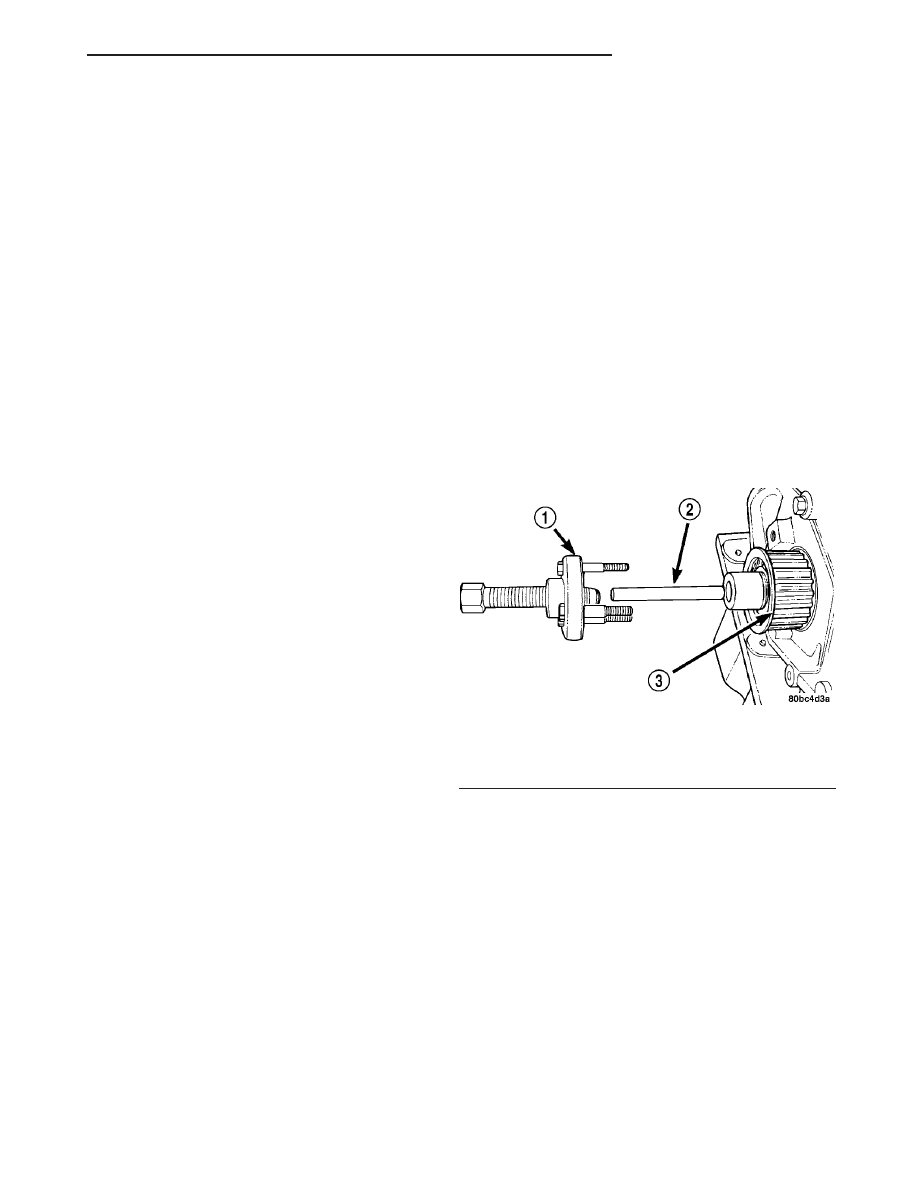
(4) Remove the crankshaft sprocket using Special

Tool 6793 and insert C-4685-C2 (Fig. 51).

(5) Remove the crankshaft sprocket key from

crankshaft (Fig. 52).

CAUTION: Do not nick shaft seal surface or seal
bore.

(6) Using Special Tool 6771, remove front crank-

shaft oil seal (Fig. 53). Do not damage the seal con-
tact area on the crankshaft.

INSTALLATION

(1) Position seal into opening with seal spring

towards the inside of engine. Using Special Tool
6780-1 (Fig. 54), install seal until flush with cover.

(2) Install the crankshaft sprocket key (Fig. 52).
(3) Install the crankshaft sprocket (Fig. 55) using

Special Tool 6792.

NOTE: Make sure the word “front” on the sprocket
is facing outward.

Fig. 51 Crankshaft Sprocket—Removal

1 - SPECIAL TOOL 6793
2 - SPECIAL TOOL C-4685–C2
3 - CRANKSHAFT SPROCKET

JR

ENGINE 2.0L DOHC

9 - 43

CRANKSHAFT (Continued)

CAUTION: Use of Special Tool 6792 is required to
install the crankshaft sprocket to the proper depth.
Failure to use this tool will cause improper timing
belt tracking.

(4) Install the timing belt. (Refer to 9 - ENGINE/

VALVE

TIMING/TIMING

BELT/CHAIN

AND

SPROCKETS - INSTALLATION)

(5) Install crankshaft vibration damper. (Refer to 9

- ENGINE/ENGINE BLOCK/VIBRATION DAMPER -
INSTALLATION)

(6) Install accessory drive belts. (Refer to 7 -

COOLING/ACCESSORY

DRIVE/DRIVE

BELTS

-

INSTALLATION)

CRANKSHAFT OIL SEAL -
REAR

REMOVAL

(1) Remove the transaxle. (Refer to 21 - TRANS-

AXLE - REMOVAL) for procedure.

(2) Remove the flex plate. (Refer to 9 - ENGINE/

ENGINE BLOCK/FLEX PLATE - REMOVAL)

Fig. 52 Crankshaft Key

1 - CRANKSHAFT KEY

Fig. 53 Front Crankshaft Oil Seal—Removal

1 - SPECIAL TOOL 6771

Fig. 54 Front Crankshaft Oil Seal - Installation

1 - PROTECTOR
2 - SEAL
3 - SPECIAL TOOL 6780–1
4 - INSTALLER

Fig. 55 Crankshaft Sprocket - Installation

1 - SPECIAL TOOL 6792

9 - 44

ENGINE 2.0L DOHC

JR

CRANKSHAFT OIL SEAL - FRONT (Continued)

(3) Insert a 3/16 flat bladed screwdriver between

the dust lip and the metal case of the crankshaft
seal. Angle the screwdriver (Fig. 56)through the dust
lip against metal case of the seal. Pry out seal.

CAUTION: Do not permit the screwdriver blade to
contact crankshaft seal surface. Contact of the
screwdriver blade against crankshaft edge (cham-
fer) is permitted.

INSTALLATION

CAUTION: If burr or scratch is present on the
crankshaft edge (chamfer), cleanup with 400 grit
sand paper to prevent seal damage during installa-
tion of new seal.

NOTE: When installing seal, no lube on seal is
needed.

(1) Place Special Tool 6926-1 on crankshaft. This is

a pilot tool with a magnetic base (Fig. 57).

(2) Position seal over pilot tool. Make sure you can

read the words THIS SIDE OUT on seal (Fig. 57).
Pilot tool should remain on crankshaft during instal-

lation of seal. Ensure that the lip of the seal is facing
towards the crankcase during installation.

CAUTION: If the seal is driven into the block past
flush, this may cause an oil leak.

(3) Drive the seal into the block using Special Tool

6926-2 and handle C-4171 (Fig. 58) until the tool bot-
toms out against the block (Fig. 59).

(4) Install the flex plate. (Refer to 9 - ENGINE/

ENGINE BLOCK/FLEX PLATE - INSTALLATION)

(5) Install the transaxle. (Refer to 21 - TRANS-

AXLE - INSTALLATION)

PISTON & CONNECTING ROD

DESCRIPTION

NOTE: The engine DOES NOT have provisions for a
free wheeling valve train. Non free wheeling valve
train means, in the event of a broken timing belt,
pistons will contact the valves.

The pistons are made of a cast aluminum alloy.

The pistons have pressed-in pins attached to forged
powdered metal connecting rods. The pistons pin is
offset 1 mm (0.0394 in.) towards the thrust side of
the piston. The connecting rods are a cracked cap
design and are not repairable. Hex head cap screws

Fig. 56 Rear Crankshaft Oil Seal—Removal

1 - REAR CRANKSHAFT SEAL
2 - ENGINE BLOCK
3 - ENGINE BLOCK
4 - REAR CRANKSHAFT SEAL METAL CASE
5 - PRY IN THIS DIRECTION
6 - CRANKSHAFT
7 - SCREWDRIVER
8 - REAR CRANKSHAFT SEAL DUST LIP
9 - SCREWDRIVER

Fig. 57 Crankshaft Rear Seal and Special Tool

6926-1

1 - SPECIAL TOOL 6926–1 PILOT
2 - SEAL

JR

ENGINE 2.0L DOHC

9 - 45

CRANKSHAFT OIL SEAL - REAR (Continued)

are used to provide alignment and durability in the
assembly. The pistons and connecting rods are ser-
viced as an assembly.

STANDARD PROCEDURE - PISTON TO
CYLINDER BORE FITTING

NOTE: Pistons and cylinder bores should be mea-
sured at normal room temperature, 70°F (21°C).

Piston and cylinder wall must be clean and dry.

Piston diameter should be measured 90 degrees to
piston pin about 14 mm (9/16 inch.) from the bottom
of the skirt as shown in (Fig. 60). Cylinder bores
should be measured halfway down the cylinder bore
and transverse (measurement location B) to the
engine crankshaft center line shown in (Fig. 61).
(Refer to 9 - ENGINE - SPECIFICATIONS) Correct
piston to bore clearance must be established in order
to assure quiet and economical operation.

REMOVAL

(1) Remove

the

cylinder

head

(Refer

to

9

-

ENGINE/CYLINDER HEAD - REMOVAL).

(2) Remove the oil pan (Refer to 9 - ENGINE/LU-

BRICATION/OIL PAN - REMOVAL).

(3) Remove top ridge of cylinder bores with a reli-

able ridge reamer before removing pistons from cyl-
inder block. Be sure to keep tops of pistons
covered during this operation
. Mark piston with
matching cylinder number (Fig. 62).

CAUTION: DO NOT use a number stamp or a punch
to mark connecting rods. Damage to connecting
rod could occur.

(4) Using a permanent ink or paint marker, iden-

tify cylinder number on each connecting rod cap (Fig.
63).

Fig. 58 Crankshaft Seal Special Tool 6926-2

1 - SPECIAL TOOL 6926–1 PILOT
2 - SEAL
3 - SPECIAL TOOL 6926–2 INSTALLER

Fig. 59 Crankshaft Rear Oil Seal - Installation

1 - SPECIAL TOOL 6926–2 INSTALLER

Fig. 60 PISTON MEASUREMENT LOCATION

1 - PISTON DIAMETER
2 - 14 mm (9/16 in.)

9 - 46

ENGINE 2.0L DOHC

JR

PISTON & CONNECTING ROD (Continued)


Content   ..  483  484  485  486   ..