Chrysler Sebring, Stratus sedan, Sebring Convertible. Manual - part 330


  Index      Chrysler     Chrysler Sebring, Stratus sedan, Sebring Convertible - service repair manual 2001-2007 year


Search            


Content   ..  328  329  330  331   ..


Chrysler Sebring, Stratus sedan, Sebring Convertible. Manual - part 330


When the above steps have been completed and the

rear glass heating grid is still inoperative, one or
more of the following is faulty:

• Rear window defogger switch in the A/C-heater

control.

• Rear window defogger timing circuitry in the

body control module (BCM).

• Rear window defogger grid lines (all grid lines

would have to be broken, or the power feed or the
ground wire disconnected, for the entire heating grid
to be inoperative).

(3) If the EBL system operation has been verified

but the rear window defogger LED indicator does not
illuminate, check fuse 6 in the JB. If the fuse is OK,
replace the A/C-heater control (Refer to 24 - HEAT-
ING

&

AIR

CONDITIONING/CONTROLS/A/C

HEATER CONTROL - REMOVAL).

REAR WINDOW DEFOGGER
RELAY

DESCRIPTION

The rear window defogger (EBL) relay (Fig. 4) is a

International

Standards

Organization

(ISO)-type

relay. Relays conforming to the ISO specifications
have common physical dimensions, current capaci-
ties, terminal functions and patterns. The EBL relay
is a electromechanical device that switches battery
current through a fuse in the power distribution cen-
ter (PDC) to the rear window defogger grid and when
equipped, to the outside mirror heating grids. The
EBL relay is energized when the relay coil is pro-

vided a ground path by the control circuitry within
the body control module (BCM).

The EBL relay is located in the junction block (JB)

in the passenger compartment.

OPERATION

The ISO-standard rear window defogger (EBL)

relay is an electromechanical switch that uses a low
current input controlled by the body control module
(BCM) to control the high current output to the rear
window defogger grid lines The movable, common
feed relay contact is held against the fixed, normally
closed relay contact by spring pressure. When the
electromagnetic relay coil is energized, it draws the
movable common feed relay contact away from the
fixed, normally closed relay contact and, holds it
against the fixed, normally open relay contact. This
action allows high current to flow to the rear window
defogger grid lines.

When the relay coil is de-energized, spring pres-

sure returns the movable relay contact back against
the fixed, normally closed contact point. The resistor
or diode is connected in parallel with the relay coil,
and helps to dissipate voltage spikes and electromag-
netic interference that can be generated as the elec-
tromagnetic field of the relay coil collapses.

The EBL relay terminals are connected to the vehi-

cle electrical system through a receptacle in the
power distribution center (PDC). The inputs and out-
puts of the EBL relay include:

• The common feed terminal (13) receives fused

battery current at all times.

• The coil ground terminal (11) receives a ground

through the EBL relay control circuit only when the
BCM electronically pulls the circuit to ground.

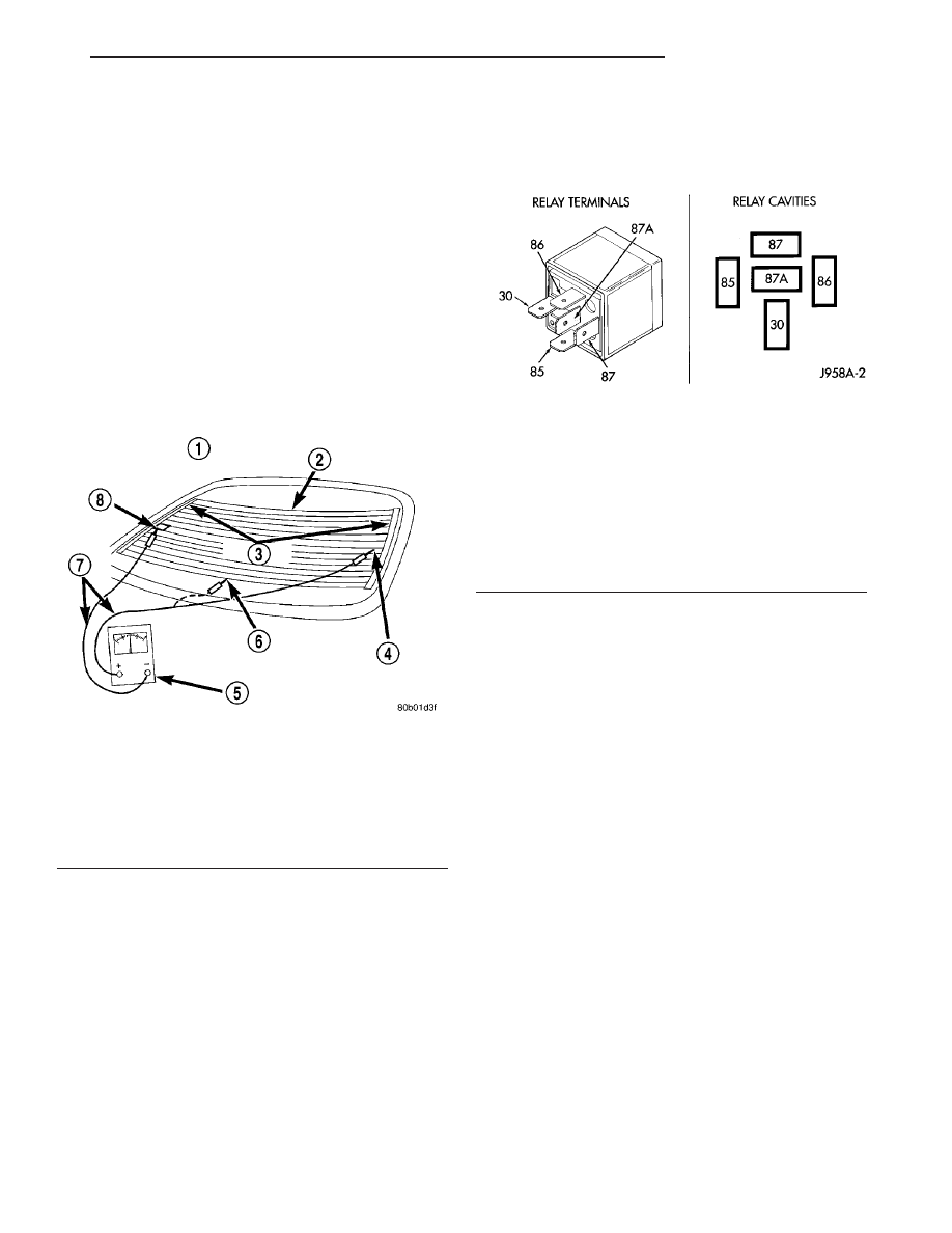
Fig. 3 Grid Line Test

1 - VIEW FROM INSIDE VEHICLE
2 - REAR WINDOW DEFOGGER
3 - BUS BARS
4 - VOLTAGE FEED (A)
5 - VOLTMETER
6 - MID-POINT (C)
7 - PICK-UP LEADS
8 - GROUND (B)

Fig. 4 Rear Window Defogger (EBL) Relay

30

COMMON FEED

85

COIL GROUND

86

COIL BATTERY

87

NORMALLY OPEN

87A

NORMALLY CLOSED

JR

HEATED GLASS

8G - 3

HEATED GLASS (Continued)

• The coil battery terminal (12) receives fused bat-

tery current through an ignition switch output circuit
only when the ignition switch is in the Run or Acc
position.

• The normally open terminal (15) provides fused

battery current to the rear window defogger grid
through the EBL relay only when the EBL relay coil
is energized.

• The normally closed terminal (15A) is not con-

nected to any circuit in this application, but provides
a battery current output only when the EBL relay
coil is de-energized.

The EBL relay cannot be repaired and, if faulty or

damaged, it must be replaced. Refer to the appropri-
ate wiring information for diagnosis and testing of
the ISO-standard relay and for complete rear window
defogger (EBL) wiring diagrams.

REMOVAL

WARNING: On vehicles equipped with airbags, dis-
able the airbag system before attempting any steer-
ing wheel, steering column, or instrument panel
component diagnosis or service. Disconnect and
isolate the battery negative (ground) cable, then
wait two minutes for the airbag system capacitor to
discharge before performing further diagnosis or
service. This is the only sure way to disable the air-
bag system. Failure to take the proper precautions
could result in an accidental airbag deployment and
possible personal injury or death.

(1) Disconnect and isolate the negative battery

cable.

(2) Remove the left instrument panel end cap

(Refer to 23 - BODY/INSTRUMENT PANEL/IN-
STRUMENT PANEL END CAP - REMOVAL).

(3) Remove the rear window defogger (EBL) relay

from the junction block (JB) (Fig. 5).

INSTALLATION

(1) Position the EBL relay into the proper recepta-

cle of the junction block (JB).

(2) Align the EBL relay terminals with the termi-

nal cavities in the JB receptacle and push down
firmly on the relay until the terminals are fully
seated.

(3) Install the instrument panel end cap (Refer to

23 - BODY/INSTRUMENT PANEL/INSTRUMENT
PANEL END CAP - INSTALLATION).

(4) Reconnect the negative battery cable.

REAR WINDOW DEFOGGER
SWITCH

DESCRIPTION

The switch for the rear window defogger (EBL)

system is integrated into the A/C-heater control (Fig.
6), which is located in the center of the instrument
panel. When the rear window defogger switch is acti-
vated, the A/C-heater control requests the body con-
trol module (BCM) to operate the rear window
defogger (EBL) relay.

When the EBL relay is activated, current is

directed to the rear defogger grid lines and the
heated side view mirrors (if equipped). The grid lines
heat the glass to help clear the surface of fog or frost.

OPERATION

An LED indicator will illuminate when the rear

window defogger switch is activated. When the
switch is activated, it energizes the timing circuit
integral to the body control module (BCM), which
then activates the rear window defogger (EBL) relay.
The EBL relay controls the current flow to the grids
of the rear window defogger and to the heated side
view mirrors, when equipped.

Fig. 5 Rear Window Defogger (EBL) Relay

1 - JUNCTION BLOCK (JB)
2 - POWER SEAT CIRCUIT BREAKER
3 - REAR WINDOW DEFOGGER (EBL) RELAY
4 - HEADLAMP DELAY RELAY
5 - HORN RELAY
6 - BODY CONTROL MODULE (BCM)

8G - 4

HEATED GLASS

JR

REAR WINDOW DEFOGGER RELAY (Continued)

NOTE: The EBL system turns off automatically after
10 minutes of initial operation. Each following acti-
vation cycle of the EBL system will last five min-
utes.

The EBL system will initially be on for approxi-

mately ten minutes or until the rear window defog-
ger switch or the ignition switch is turned off. After
the initial time interval has expired, if the defogger
switch is turned On again during the same ignition
cycle, the EBL system will automatically turn off
after about five minutes.

The rear window defogger switch and the rear win-

dow defogger LED indicator cannot be repaired and,
if faulty or damaged, the A/C-heater control must be
replaced (Refer to 24 - HEATING & AIR CONDI-
TIONING/CONTROLS/CONTROL-A/C

HEATER

-

REMOVAL).

DIAGNOSIS AND TESTING

REAR WINDOW DEFOGGER SWITCH

The rear window defogger switch and timer circuit

may be tested in the vehicle with or without the DRB
III

t scan tool.

TESTING WITH SCAN TOOL

Using a DRB III

t scan tool, refer to the proper

Body Diagnostic Procedures Manual.

TESTING WITHOUT SCAN TOOL

NOTE: For circuit descriptions and diagrams of the
rear window defogger (EBL) system, refer to 8W -
WIRING DIAGRAM INFORMATION.

(1) Remove the A/C-heater control from the instru-

ment panel.

(2) Using a ohmmeter, check between Pins 6 and 1

of the A/C-heater control electrical connector. Depress
the rear window defogger switch. The resistance
reading should be 360 ohms (± 10%). If not OK,
replace the A/C-heater control. If OK, check for the
following:

• Faulty rear window defogger (EBL) relay

• Faulty fuse in the junction block (JB)

• Open circuit

• Short circuit

• Faulty connection

• Faulty body control module (BCM)

REAR WINDOW DEFOGGER
GRID LINES

STANDARD PROCEDURE

GRID LINE AND TERMINAL REPAIR

REAR WINDOW DEFOGGER GRID LINE REPAIR

WARNING: Materials contained in the Repair Kit
(Part Number 04549275) may cause skin or eye irri-
tation. The kit contains epoxy resin and amine type
hardener, which are harmful if swallowed. Avoid
contact with the skin and eyes. For skin contact,
wash the affected areas with soap and water. For
contact with the eyes, flush with plenty of water. Do
not take internally. If taken internally, induce vomit-
ing and call a physician immediately. Use with ade-
quate ventilation. Do not use near fire or flame.
Contains flammable solvents. Keep out of the reach
of children. Failure to follow the warnings could
result in possible personal injury or death.

Repair of the rear glass heating grid lines and bus

bars can be accomplished using the Mopar

t Rear

Window

Defogger

Repair

Kit

(Part

Number

04549275) or equivalent.

(1) Mask the repair area with masking tape or use

a template so that the conductive epoxy can be
applied neatly (Fig. 7). Extend the epoxy application
onto the grid line or the bus bar on each side of the
break.

(2) Follow the instructions in the repair kit for

preparing the damaged area.

Fig. 6 Rear Window Defogger Switch

1 - A/C-HEATER CONTROL
2 - REAR WINDOW DEFOGGER SWITCH

JR

HEATED GLASS

8G - 5

REAR WINDOW DEFOGGER SWITCH (Continued)

(3) Remove the package separator clamp and mix

the two conductive epoxy components thoroughly
within the packaging. Fold the package in half and
cut the center corner to dispense the epoxy.

(4) Apply the epoxy through the slit in the mask-

ing tape or template. Overlap both ends of the break
by at least 19 millimeters (0.75 inch).

(5) Apply a thin layer of conductive epoxy to the

terminal or bare wire end of the pigtail and place it
in the proper location on the bus bar. To prevent the
terminal or pigtail wire from moving while the epoxy
is curing, it must be wedged or clamped.

(6) Carefully remove the masking tape or tem-

plate.

CAUTION: Do not allow the glass surface to exceed
204° C (400° F) when using a heat gun, or the glass
may fracture.

(7) Allow the epoxy to cure 24 hours at room tem-

perature, or carefully use a heat gun for fifteen min-
utes. When using a heat gun, hold it approximately
25.4 centimeters (10 inches) from the repair and do
not allow the glass surface to exceed 204° C (400° F).

(8) After the conductive epoxy is properly cured,

check the operation of the rear window defogger
glass heating grid.

REAR WINDOW DEFOGGER TERMINAL REPAIR - HARD TOP
MODELS

WARNING: Materials contained in the Repair Kit
(Part Number 04549275) may cause skin or eye irri-
tation. The kit contains epoxy resin and amine type
hardener, which are harmful if swallowed. Avoid
contact with the skin and eyes. For skin contact,
wash the affected areas with soap and water. For
contact with the eyes, flush with plenty of water. Do
not take internally. If taken internally, induce vomit-

ing and call a physician immediately. Use with ade-
quate ventilation. Do not use near fire or flame.
Contains flammable solvents. Keep out of the reach
of children. Failure to follow the warnings could
result in possible personal injury or death.

Repair of the rear glass heating grid terminal(s) on

hard top models can be accomplished using the
Mopar

t Rear Window Defogger Repair Kit (Part

Number 04549275) or equivalent.

(1) If the grid terminal(s) is broken and a portion

of the terminal is still attached to the heating grid,
remove the portion of the clip remaining in the wire
harness connector(s).

(2) Mask the areas so the conductive epoxy can be

extended onto the adjacent grid line(s) as well as the
bus bar.

(3) Apply a thin layer of conductive epoxy to the

area where the terminal(s) where fastened and to the
adjacent grid line(s).

NOTE: To prevent the terminal(s) from moving while
the epoxy is curing, a wedge or clamp must be
used.

(4) Apply a thin layer of conductive epoxy on the

terminal(s) and properly orient the terminal(s) at the
desired location(s).

(5) Carefully remove the masking tape.

CAUTION: Do not allow the glass surface to exceed
204° C (400° F) when using a heat gun, or the glass
may fracture.

(6) Allow the epoxy to cure 24 hours at room tem-

perature, or carefully use a heat gun for fifteen min-
utes. When using a heat gun, hold it approximately
25.4 centimeters (10 inches) from the repair and do
not allow the glass surface to exceed 204° C (400° F).

NOTE: To ensure proper installation, do not attach
the wire harness connector(s) to the terminal(s)
until the epoxy is completely cured.

(7) After the conductive epoxy has properly cured,

remove the wedge or clamp from the terminal(s),
reconnect the wire harness connector(s) and verify
operation of the rear window defogger.

REAR WINDOW DEFOGGER TERMINAL REPAIR -
CONVERTIBLE MODELS

CAUTION: Do not use a flame type solder gun or an
electric solder gun rated greater than 500 watts or
damage to the glass may occur.

If the rear window defogger grid terminal(s) on

convertible models is damaged or separated from the
rear window, the new grid terminal(s) must be

Fig. 7 Grid Line Repair

1 - BREAK
2 - GRID LINE
3 - MASKING TAPE

8G - 6

HEATED GLASS

JR

REAR WINDOW DEFOGGER GRID LINES (Continued)


Content   ..  328  329  330  331   ..