Chrysler Sebring, Stratus sedan, Sebring Convertible. Manual - part 329


  Index      Chrysler     Chrysler Sebring, Stratus sedan, Sebring Convertible - service repair manual 2001-2007 year


Search            


Content   ..  327  328  329  330   ..


Chrysler Sebring, Stratus sedan, Sebring Convertible. Manual - part 329


INSTALLATION

INSTALLATION - 4 CYLINDER

(1) Connect solenoid and B+ wires to starter termi-

nals.

(2) Install nut holding B+ wire to terminal.
(3) Connect solenoid wire connector to terminal
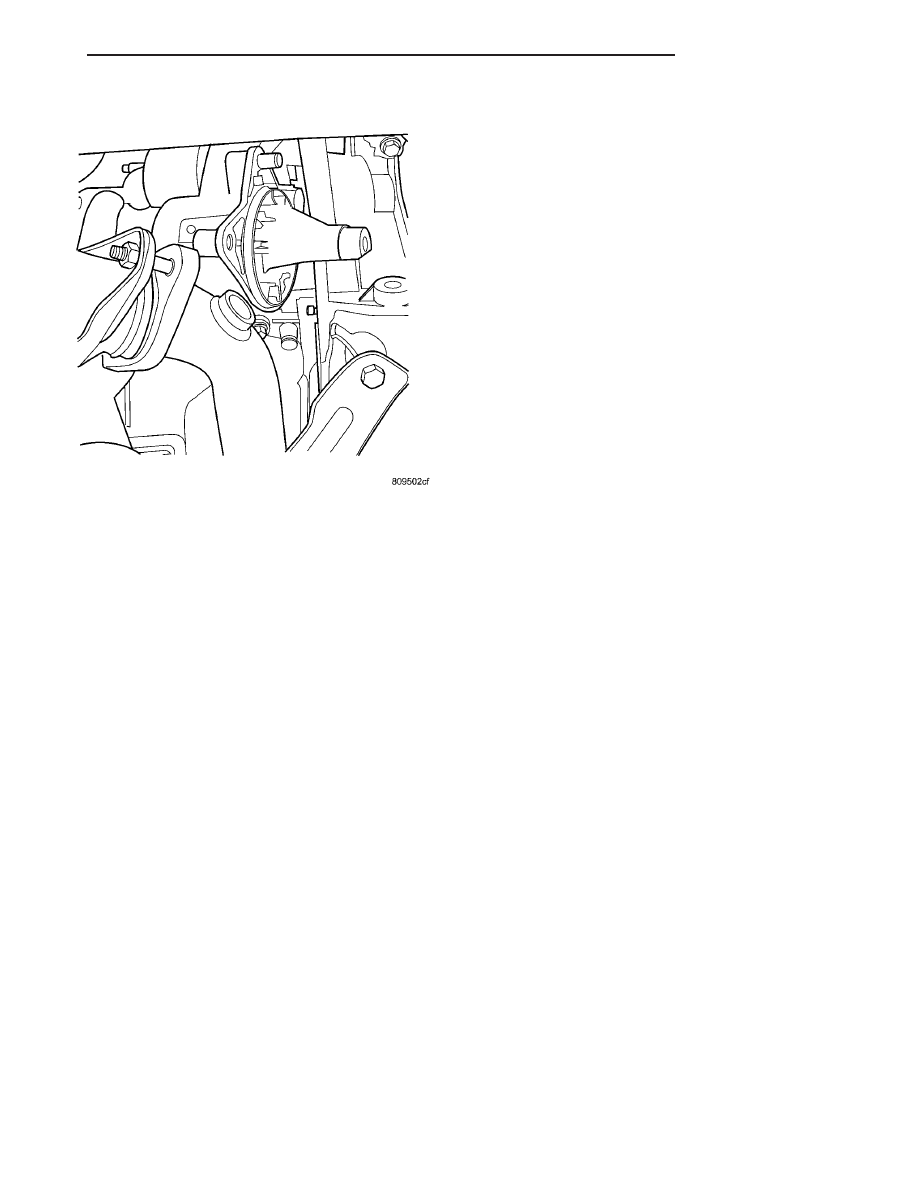
(4) Install starter (Fig. 3).
(5) Install the upper bolt.
(6) Install the lower bolt.
(7) Install the air cleaner box.
(8) Connect the battery negative cable.

INSTALLATION - 2.7L

(1) Install starter to transmission.
(2) Start the upper starter bolt.
(3) Start the lower bolt and snug it so that the

starter will not move.

(4) Remove the upper bolt.

(5) Connect the battery cable and torque nut to 8.5

N·m (75 in. lbs.).

(6) Install the front mount bracket and check heat

shield location.

(7) Install bolt the upper bolt and torque bolt to 54

N·m (40 ft. lbs.)

(8) Install the lower and torque bolt to 54 N·m (40

ft. lbs.)

(9) Install the front mount through bolt and torque

bolt to 61 N·m (45 ft.. lbs.)

(10) Install the O2 sensor and torque to 27 N·m

(20 ft. lbs.)

(11) Lower vehicle.
(12) Connect the negative battery cable.

STARTER MOTOR RELAY

DESCRIPTION

The Starter Relay is a micro relay located in the

Power Distribution Center (PDC), positioned in the
left front corner of the engine compartment.

OPERATION

As battery power is applied to the relay from the

ignition switch, battery power is applied to the
starter motor through the relay to the starter sole-
noid.

REMOVAL

The relay is located in the Power Distribution Cen-

ter (PDC). Refer to the PDC cover for relay location.

STARTER SOLENOID

OPERATION

The Starter Solenoid is a switching device used to

activate the high amperage starter motor circuit from
a low amperage control circuit.

Fig. 6 STARTER MOTOR REMOVAL

JR

STARTING

8F - 31

STARTER MOTOR (Continued)

HEATED SYSTEMS

TABLE OF CONTENTS

page

page

HEATED GLASS . . . . . . . . . . . . . . . . . . . . . . . . . . . 1
HEATED MIRRORS . . . . . . . . . . . . . . . . . . . . . . . . . 8

HEATED SEAT SYSTEM . . . . . . . . . . . . . . . . . . . . . 9

HEATED GLASS

TABLE OF CONTENTS

page

page

HEATED GLASS

DESCRIPTION

. . . . . . . . . . . . . . . . . . . . . . . . . . 1

OPERATION

. . . . . . . . . . . . . . . . . . . . . . . . . . . . 2

DIAGNOSIS AND TESTING

ELECTRIC BACKLIGHT (EBL) SYSTEM

. . . . . 2

REAR WINDOW DEFOGGER RELAY

DESCRIPTION

. . . . . . . . . . . . . . . . . . . . . . . . . . 3

OPERATION

. . . . . . . . . . . . . . . . . . . . . . . . . . . . 3

REMOVAL

. . . . . . . . . . . . . . . . . . . . . . . . . . . . . 4

INSTALLATION

. . . . . . . . . . . . . . . . . . . . . . . . . . 4

REAR WINDOW DEFOGGER SWITCH

DESCRIPTION

. . . . . . . . . . . . . . . . . . . . . . . . . . 4

OPERATION

. . . . . . . . . . . . . . . . . . . . . . . . . . . . 4

DIAGNOSIS AND TESTING

REAR WINDOW DEFOGGER SWITCH

. . . . . . 5

REAR WINDOW DEFOGGER GRID LINES

STANDARD PROCEDURE

GRID LINE AND TERMINAL REPAIR

. . . . . . . . 5

HEATED GLASS

DESCRIPTION

CAUTION: Grid lines can be damaged or scraped
off with sharp instruments. Care should be taken in
cleaning

glass

or

removing

foreign

materials,

decals or stickers. Normal glass cleaning solvents
or hot water used with rags or toweling is recom-
mended.

The rear window defogger system, also known as

electric backlight (EBL), consists of two vertical bus
bars linked by a series of grid lines fired onto the
inside surface of the rear window (Fig. 1).

The EBL system is turned On and Off by a switch

in the A/C-heater control located at the center of the
instrument panel and by a timing circuit integral to
the body control module (BCM).

Circuit protection is provided by two cartridge

fuses. The fuse located in the junction block (JB) is
for the control circuit and the fuse located in the
power distribution center (PDC) is for the heated
grid circuit.

Fig. 1 Rear Window Defogger (EBL) System -

Typical

1 - VERTICAL BUS BARS
2 - GRID LINES
3 - REAR WINDOW GLASS

JR

HEATED SYSTEMS

8G - 1

OPERATION

The electric backlight (EBL) system is controlled

by a momentary switch located in the A/C-heater
control on the instrument panel (Fig. 2). When the
rear window defogger switch is pressed to the On
position, the body control module (BCM) energizes
the rear window defogger (EBL) relay and battery
current is then directed through the relay and to the
rear defogger grid lines and when equipped, the
heated side view mirrors. The grid lines heat the
glass to help clear the rear window and side view
mirror surfaces of fog or frost.

An amber indicator in the rear window defogger

switch will illuminate to indicate when the EBL sys-
tem is turned on. The BCM contains the defogger
system control circuitry including the timer logic.

NOTE: The EBL system turns off automatically after
10 minutes of initial operation. Each following acti-
vation cycle of the EBL system will last five min-
utes.

The EBL system will be automatically turned off

after an initial programmed time interval of about
ten minutes. After the initial time interval has
expired, if the rear window defogger switch is turned
on again during the same ignition cycle, the EBL sys-
tem will automatically turn off after about five min-
utes. The EBL system will automatically shut off if
the ignition switch is turned to the Off position, or it
can be turned off manually by pressing the rear win-
dow defogger switch a second time.

Repair of the rear defogger grid lines, bus bars,

terminals or pigtail wires can be accomplished using
the Mopar Rear Window Defogger Repair Kit (Part
Number 04549275) or equivalent (Refer to 8 - ELEC-
TRICAL/HEATED GLASS/REAR WINDOW DEFOG-
GER GRID - STANDARD PROCEDURE - GRID
LINE AND TERMINAL REPAIR).

DIAGNOSIS AND TESTING

ELECTRIC BACKLIGHT (EBL) SYSTEM

NOTE: Illumination of the defogger switch indicator
lamp does not necessary mean that electrical cur-
rent is reaching the rear glass heating grid lines.

NOTE: For circuit descriptions and diagrams of the
rear window defogger system, refer to 8W - WIRING
DIAGRAM INFORMATION.

Operation of the electric backlight (EBL) system

can be confirmed by the following:

(1) Turn the ignition switch to the On position. Set

the rear window defogger switch in the On position.
The rear window defogger operation can be checked
by feeling the surfaces of the rear window glass or
outside rear view mirror glass. A distinct difference
in temperature between the grid lines and the adja-
cent clear glass or the mirror glass should be
detected within three to four minutes of operation.

(2) If a temperature difference is not detected, use

a 12-volt DC voltmeter and contact the rear glass
heating grid power feed terminal A with the positive
lead, and the ground terminal B with the negative
lead (Fig. 3). The voltmeter should read battery volt-
age. If the voltmeter does not read battery voltage,
check the following:

• Confirm that the ignition switch is in the On

position.

• Make sure that the rear glass heating grid feed

wire and ground wire are connected to the terminals.
Confirm that the ground wire has continuity to
ground.

• Check the EBL relay and fuse located in the

junction block (JB) in the passenger compartment.
Check the fuse in the power distribution center
(PDC) located in the engine compartment. The relay
and fuses must be tight in their receptacles and all
electrical connections must be secure. Refer to the
appropriate wiring information for diagnosis and
testing of the ISO-standard relay.

Fig. 2 Rear Window Defogger Switch - Manual

Control Shown

1 - A/C-HEATER CONTROL
2 - REAR WINDOW DEFOGGER SWITCH

8G - 2

HEATED GLASS

JR

HEATED GLASS (Continued)


Content   ..  327  328  329  330   ..