Chrysler Sebring, Stratus sedan, Sebring Convertible. Manual - part 309


  Index      Chrysler     Chrysler Sebring, Stratus sedan, Sebring Convertible - service repair manual 2001-2007 year


Search            


Content   ..  307  308  309  310   ..


Chrysler Sebring, Stratus sedan, Sebring Convertible. Manual - part 309


(4) Disconnect the overflow hose from coolant out-

let connector.

(5) Remove coolant recovery container screws.
(6) Remove coolant recovery container.

INSTALLATION

(1) Install container in mounting position and

install attaching screws.

(2) Connect the overflow hose to the coolant outlet

connector.

(3) Snap the washer hose into groove on coolant

recovery container.

(4) Install

the

air

conditioning

receiver/dryer

attaching screw.

(5) Install the power steering reservoir attaching

screw.

(6) Fill cooling system (Refer to 7 - COOLING/EN-

GINE - STANDARD PROCEDURE).

COOLANT PRESSURE
CONTAINER - 2.7L

DESCRIPTION

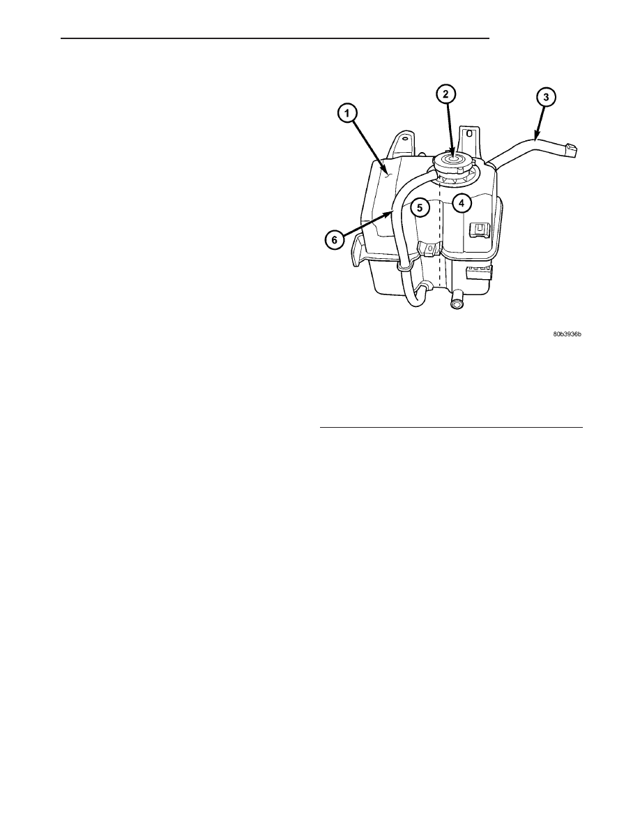
The coolant pressure container consists of a pres-

sure chamber and a overflow chamber (Fig. 14). The
coolant pressure container is mounted in the right
side engine compartment. An overflow hose connects
the pressure chamber to the overflow chamber.

NOTE: Coolant will normally be in the pressure
chamber side of the coolant bottle. The overflow
chamber should normally be empty

OPERATION

The pressure chamber keeps the coolant free of

trapped air, provides a volume for expansion and con-
traction, and provides a convenient and safe method
for checking and adjusting coolant level at atmo-
spheric pressure. It also provides some reserve cool-
ant to cover minor leaks, evaporation or boiling
losses. The overflow chamber allows coolant recovery
in case of an overheat.

REMOVAL

(1) Drain coolant below the coolant pressure con-

tainer level.

(2) Remove the power steering reservoir attaching

screw.

(3) Remove

the

air

conditioning

receiver/dryer

attaching screw.

(4) Unsnap washer hose from the bottle.
(5) Disconnect the hose from coolant outlet connec-

tor to the bottle.

(6) Remove pressure container attaching screws.

(7) Reposition pressure container and disconnect

the heater hose at the container.

(8) Remove coolant pressure container.

INSTALLATION

(1) Connect heater hose to coolant pressure con-

tainer.

(2) Install container in mounting position and

install attaching screws.

(3) Connect the coolant outlet connector hose to

the bottle.

(4) Snap washer hose into groove on coolant pres-

sure container.

(5) Install

the

air

conditioning

receiver/dryer

attaching screw.

(6) Install the power steering reservoir attaching

screw.

(7) Fill cooling system (Refer to 7 - COOLING/EN-

GINE - STANDARD PROCEDURE).

Fig. 14 Coolant Pressure Container - 2.7L

1 - COOLANT PRESSURE CONTAINER
2 - COOLANT PRESSURE CAP
3 - HOSE TO COOLANT OUTLET CONNECTOR
4 - PRESSURE CHAMBER
5 - OVERFLOW CHAMBER
6 - OVERFLOW HOSE

JR

ENGINE

7 - 29

COOLANT RECOVERY CONTAINER - 2.0L/2.4L (Continued)

ENGINE BLOCK HEATER

DESCRIPTION

DESCRIPTION - 2.0L/2.4L

The block heater is operated by ordinary house

current (110 Volt A.C.) through a power cord and con-
nector located in the engine compartment. The
heater is mounted in a core hole (in place of a core
hole plug) in the engine block, with the heating ele-
ment immersed in coolant (Fig. 15).

CAUTION: The power cord must be secured in its
retainer clips, and not positioned so it could con-
tact linkages or exhaust manifolds and become
damaged.

DESCRIPTION - 2.7L

The engine block heater is mounted in the cylinder

block, near the right rear corner (Fig. 16). The block
heater is a dry cylinder type design and is powered
by 110 volt AC. The power cord must be secured
in its retainer clips, and not positioned so it
could contact linkages or exhaust manifolds
and become damaged.

OPERATION

OPERATION - 2.0L/2.4L

The block heater element is submerged in the cool-

ing system’s coolant. When electrical power (110 volt
A.C.) is applied to the element, it creates heat. This
heat is transferred to the engine coolant. This pro-
vides easier engine starting and faster warm-up
when vehicle is operated in areas having extremely
low temperatures.

OPERATION - 2.7L

When power is applied (110 volt A.C.) to the block

heater, the heating element transfers heat through
the aluminum engine block and into the coolant
without directly penetrating the cooling system.

DIAGNOSIS AND TESTING - ENGINE BLOCK
HEATER TESTING

If unit does not operate, trouble can be in either

the power cord or the heater element. Test power
cord for continuity with a 110-volt voltmeter or 110-
volt test light; test heater element continuity with an
ohmmeter or 12-volt test light.

REMOVAL

REMOVAL - 2.0L/2.4L

(1) Drain cooling system (Refer to 7 - COOLING/

ENGINE - STANDARD PROCEDURE).

(2) Raise vehicle on hoist.
(3) Detach power cord plug from heater.
(4) Loosen screw in center of heater. Remove

heater assembly (Fig. 15).

REMOVAL - 2.7L

(1) Raise vehicle on hoist.
(2) Detach power cord plug from heater (Fig. 16).
(3) Remove block heater attaching screw located

below heater terminals.

(4) Remove block heater from cylinder block.

Fig. 15 Engine Block Heater

1 - BLOCK HEATER
2 - POWER CORD

Fig. 16 ENGINE BLOCK HEATER

1 - BLOCK HEATER
2 - ENGINE — RIGHT SIDE

7 - 30

ENGINE

JR

INSTALLATION

INSTALLATION - 2.0L/2.4L

(1) Thoroughly clean core hole and heater seat.
(2) Insert heater assembly with element loop posi-

tioned upward (Fig. 15).

(3) With

heater

seated,

tighten

center

screw

securely to assure a positive seal.

CAUTION: To prevent damage, the power cord must
be secured in it’s retaining clips, and not positioned
so it could contact linkages or exhaust manifold.

(4) Connect power cord to heater.
(5) Lower vehicle.
(6) Fill cooling system (Refer to 7 - COOLING/EN-

GINE - STANDARD PROCEDURE).

INSTALLATION - 2.7L

(1) Thoroughly clean cylinder block heater cavity.
(2) Insert heater assembly into block such that

mounting hole is located below heater terminals (Fig.
16).

(3) Install mounting screw and tighten to 12 N·m

(105 in. lb.).

CAUTION: To prevent damage, the power cord must
be secured in its retainer clips, and not positioned
so it could contact linkages or exhaust manifolds.

(4) Attach power cord to heater.
(5) Lower vehicle.

ENGINE COOLANT
TEMPERATURE SENSOR

DESCRIPTION

2.0L/2.4L ENGINE

The Engine Coolant Temperature (ECT) Sensor

threads into the thermostat housing just below the
coolant outlet connector (Fig. 17). The ECT Sensor is
a negative thermal coefficient sensor.

2.7L ENGINE

The Engine Coolant Temperature (ECT) Sensor

threads into the coolant outlet connector (Fig. 18).
The ECT Sensor is a negative thermal coefficient
sensor.

OPERATION

The ECT sensor provides an input to the PCM. As

temperature

increases,

resistance

of

the

sensor

decreases. As coolant temperature varies, the ECT
sensor resistance changes resulting in a different

voltage value at the PCM ECT sensor signal circuit.
The ECT sensor provides input for various PCM
operations. The PCM uses the input to control air-
fuel mixture, timing, and radiator fan on/off times.
The PCM uses ECT sensor input to send messages
over the PCI bus to various modules for other func-
tions such as temperature gauge and AC operation.

REMOVAL

(1) With engine cold, partially drain cooling system

below level of ECT sensor.

(2) Disconnect ECT sensor electrical connector

(Fig. 17) or (Fig. 18).

(3) Remove ECT sensor.

Fig. 17 ECT SENSOR 2.0L/2.4L

Fig. 18 ECT SENSOR 2.7L

JR

ENGINE

7 - 31

ENGINE BLOCK HEATER (Continued)

INSTALLATION

(1) Install ECT sensor. Torque sensor to 19 N·m

(168 in. lbs.).

(2) Reconnect ECT sensor electrical sensor.
(3) Fill cooling system (Refer to 7 - COOLING/EN-

GINE - STANDARD PROCEDURE).

ENGINE COOLANT
THERMOSTAT

DESCRIPTION

DESCRIPTION - 2.0L/2.4L

The thermostat is located on the front of the

engine (radiator side) in the thermostat housing/cool-
ant outlet connector (Fig. 19). The thermostat has a
air bleed vent located in the flange and an O-ring
with a locating dimple incorporated on it. There is a
relief in the housing for positioning the air bleed.

DESCRIPTION - 2.7L

The thermostat is located on the lower left side of

engine, near the front (Fig. 20). The thermostat is on
the inlet side of the water pump. It has an air bleed
located in the thermostat flange. The air bleed allows
internal trapped air during cooling system filling to
be released.

OPERATION

The engine cooling thermostat is a wax pellet

driven, reverse poppet choke type. The thermostat is
designed to provide the fastest warm up possible by
preventing leakage through it and to guarantee a
minimum engine operating temperature of 88 to
93°C (192 to 199°F). The thermostat also will auto-
matically reach wide open so it will not restrict flow
to the radiator as temperature of the coolant rises in
hot weather to around 104°C (220°F). Above this
temperature the coolant temperature is controlled by
the radiator, fan, and ambient temperature, not the
thermostat.

The thermostat is operated by a wax filled con-

tainer (pellet) which is sealed. When heated coolant
reaches

a

predetermined

temperature,

the

wax

expands enough to overcome the closing spring and
water pump pressure, which forces the valve to open.

DIAGNOSIS AND TESTING - ENGINE COOLANT
THERMOSTAT TESTING

The thermostat is operated by a wax filled con-

tainer (pellet) which is sealed. When heated coolant
reaches a predetermined temperature the wax pellet
expands enough to overcome the closing spring and

water pump pressure, which forces the valve to open.
Coolant leakage into the pellet will cause a thermo-
stat to fail open. Do not attempt to free up a thermo-
stat with a screwdriver.

The thermostat that opens too soon type failure

mode is included in the on-board diagnosis. The
check engine light will not be lit by an open too soon
condition. If it has failed open, a diagnostic trouble
code (DTC) will be set. Do not change a thermostat
for lack of heater performance or temperature gauge
position, unless a DTC is present. For other probable
causes, (Refer to 7 - COOLING/ENGINE - DIAGNO-
SIS AND TESTING). Thermostat failing shut is the
normal long term mode of failure, and normally, only
on high mileage vehicles. The temperature gauge will
indicate this. (Refer to 7 - COOLING/ENGINE -
DIAGNOSIS AND TESTING)

REMOVAL

REMOVAL - 2.0L/2.4L

WARNING: DO NOT REMOVE PRESSURE CAP OR
ANY HOSE WITH THE SYSTEM HOT AND UNDER
PRESSURE

BECAUSE

SERIOUS

BURNS

FROM

COOLANT CAN OCCUR.

(1) Partially drain cooling system below thermo-

stat level.

(2) Disconnect hoses at coolant outlet connector.
(3) Remove bolts attaching coolant outlet connector

(Fig. 19).

(4) Remove coolant outlet connector and thermo-

stat.

REMOVAL - 2.7L

(1) Disconnect negative cable from remote jumper

terminal.

WARNING: DO NOT REMOVE PRESSURE CAP OR
ANY HOSE WITH THE SYSTEM HOT AND UNDER
PRESSURE

BECAUSE

SERIOUS

BURNS

FROM

COOLANT CAN OCCUR.

(2) Drain cooling system (Refer to 7 - COOLING/

ENGINE - STANDARD PROCEDURE).

(3) Raise vehicle on hoist.
(4) Remove right front wheel and belt splash

shield.

(5) Remove accessory drive belts (Refer to 7 -

COOLING/ACCESSORY

DRIVE/DRIVE

BELTS

-

REMOVAL).

(6) Remove lower generator mounting bolt.
(7) Lower vehicle.
(8) Disconnect generator electrical connectors.

7 - 32

ENGINE

JR

ENGINE COOLANT TEMPERATURE SENSOR (Continued)


Content   ..  307  308  309  310   ..