Chrysler Sebring, Stratus sedan, Sebring Convertible. Manual - part 308


  Index      Chrysler     Chrysler Sebring, Stratus sedan, Sebring Convertible - service repair manual 2001-2007 year


Search            


Content   ..  306  307  308  309   ..


Chrysler Sebring, Stratus sedan, Sebring Convertible. Manual - part 308


(4) Remove cooling system pressure cap and fill

cooling system with recommended coolant.

(5) Slowly continue filling until a steady stream of

coolant flows from attached hose on bleed valve.

(6) Close bleed valve and remove hose.
(7) Fill coolant to the top of pressure cap neck.
(8) Install cooling system pressure cap.
(9) Fill coolant recovery container to the MAX

mark.

(10) Start engine and allow to run until thermo-

stat opens and radiator fans cycle.

NOTE: It may be necessary to add additional cool-
ant to the coolant recovery container after three or
four warm-up/cool down cycles to maintain coolant
level between the MIN and MAX marks; as addi-
tional trapped air is removed from the system.

FILLING - 2.7L

(1) Close radiator draincock by turning clockwise.

NOTE: IT IS IMPERATIVE THAT THE COOLING SYS-
TEM AIR BLEED VALVE BE OPENED BEFORE ANY
COOLANT IS ADDED TO THE COOLING SYSTEM.
FAILURE TO OPEN THE BLEED VALVE FIRST WILL
RESULT IN AN INCOMPLETE FILL OF THE SYSTEM.

(2) Open cooling system bleed valve (Fig. 9).

(3) Attach a 6.35 mm (0.250 in.) inside diameter

clear hose that is 120.0 cm (48 in.) long to the bleed
valve. Route the hose away from accessory drive
belts and radiator fan. Position the other end of hose
into a collecting container. The hose will prevent cool-
ant from contacting accessory drive belts and other
components.

(4) Remove cooling system pressure cap. Attach

Special Tool 8195, Filling Aid Funnel to coolant pres-
sure container filler neck.

(5) Use the supplied clip to pinch overflow hose

that connects between the two chambers of the pres-
sure container (Fig. 9).

(6) Pour coolant into the larger section of Filling

Aid Funnel (the smaller section of funnel is to allow
air to escape).

(7) Slowly continue filling until a steady stream of

coolant flows from attached hose on bleed valve.

(8) Close bleed valve and continue filling system to

top of Filling Aid Funnel.

(9) Remove clip from overflow hose.
(10) Allow coolant in Filling Aid Funnel to drain

into overflow chamber of pressure container.

(11) Remove Special Tool 8195, Filling Aid Funnel

and install pressure cap on pressure container.

(12) Remove hose from bleed valve.
(13) Start engine and allow to run until thermo-

stat opens and radiator fans cycle.

NOTE:
The engine cooling system will push any remaining
air into the pressure container within about one half
hour of normal driving. As a result, a drop in cool-
ant level in the pressure container may occur.
If the engine cooling system overheats and pushes
coolant into the overflow chamber of the pressure
container, this coolant will be sucked back into the
cooling system ONLY IF THE PRESSURE CAP IS
LEFT ON THE PRESSURE CONTAINER. Removing
the pressure cap breaks the vacuum path between
the two chambers of the pressure container and the
coolant will not return to the cooling system.

(14) Shut off engine and allow it to cool down. This

permits coolant to be drawn into the pressure cham-
ber.

(15) With engine COLD, observe coolant level in

pressure chamber. Coolant level should be within
MIN and MAX marks. Adjust coolant level as neces-
sary.

CLEANING

Drain cooling system and refill with clean water.

Refer to drain and fill procedures in this section. Run
engine with radiator cap installed until upper radia-
tor hose is hot. Stop engine and drain water from
system. If water is dirty; fill, run, and drain system

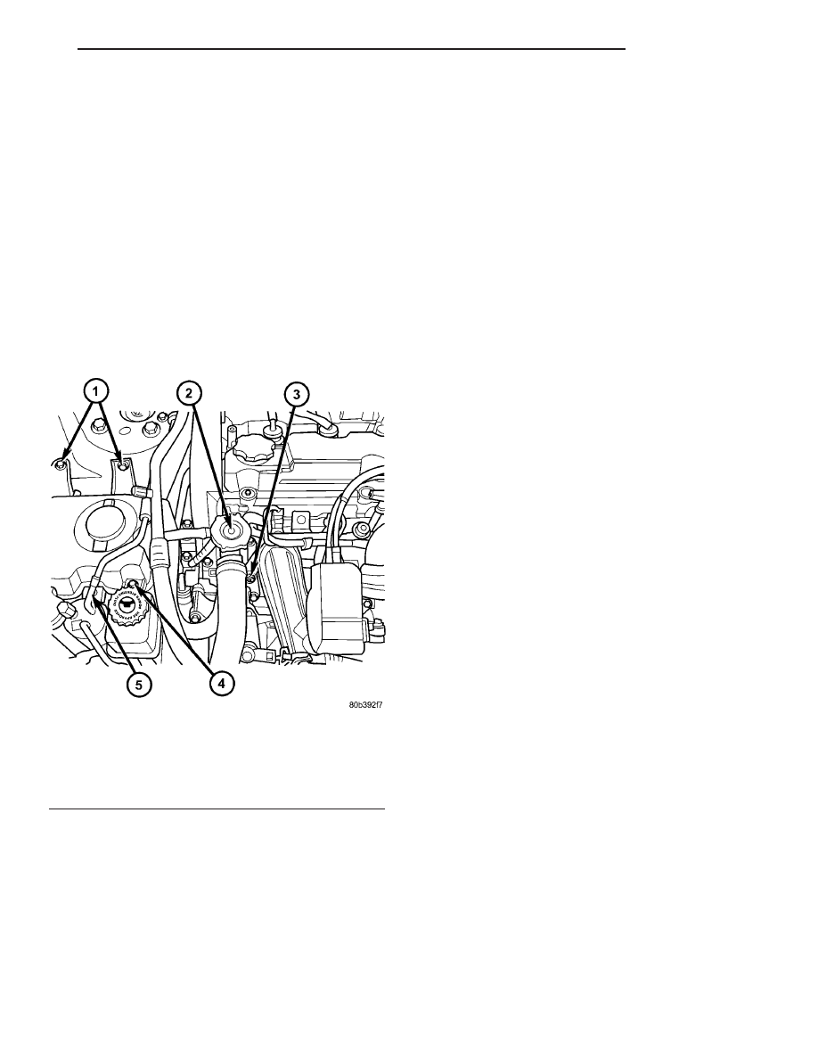
Fig. 8 Cooling System Filling - 2.0L/2.4L

1 - COOLANT RECOVERY CONTAINER FASTENERS
2 - COOLANT PRESSURE CAP
3 - COOLING SYSTEM BLEED VALVE
4 - POWER STEERING RESERVIOR FASTENER
5 - RECEIVER/DRIER FASTENER

JR

ENGINE

7 - 25

ENGINE (Continued)

again, until water runs clear. Refill cooling system
with a 50/50 mixture of the recommended ethylene
glycol and distilled water (Refer to LUBRICATION &
MAINTENANCE/FLUID TYPES - DESCRIPTION).

INSPECTION

After

performing

a

cleaning/flush

procedure,

inspect all hoses, clamps and connections for deterio-
ration and leaks. Inspect radiator and heater core for
leaks.

COOLANT

DESCRIPTION - ENGINE COOLANT

WARNING: ANTIFREEZE IS AN ETHYLENE GLYCOL
BASE COOLANT AND IS HARMFUL IF SWAL-
LOWED OR INHALED. IF SWALLOWED, DRINK
TWO GLASSES OF WATER AND INDUCE VOMIT-
ING. IF INHALED, MOVE TO FRESH AIR AREA.
SEEK MEDICAL ATTENTION IMMEDIATELY. DO NOT
STORE IN OPEN OR UNMARKED CONTAINERS.
WASH SKIN AND CLOTHING THOROUGHLY AFTER
COMING IN CONTACT WITH ETHYLENE GLYCOL.
KEEP OUT OF REACH OF CHILDREN. DISPOSE OF
GLYCOL BASE COOLANT PROPERLY, CONTACT
YOUR DEALER OR GOVERNMENT AGENCY FOR
LOCATION OF COLLECTION CENTER IN YOUR

AREA. DO NOT OPEN A COOLING SYSTEM WHEN
THE ENGINE IS AT OPERATING TEMPERATURE OR
HOT UNDER PRESSURE, PERSONAL INJURY CAN
RESULT. AVOID RADIATOR COOLING FAN WHEN
ENGINE COMPARTMENT RELATED SERVICE IS
PERFORMED, PERSONAL INJURY CAN RESULT.

CAUTION: Use of Propylene Glycol based coolants
is not recommended, as they provide less freeze
protection and less boiling protection.

The cooling system is designed around the coolant.

The coolant must accept heat from engine metal, in
the cylinder head area near the exhaust valves and
engine block. Then coolant carries the heat to the
radiator where the tube/fin radiator can transfer the
heat to the air.

The use of aluminum cylinder blocks, cylinder

heads, and water pumps requires special corrosion
protection.

Mopar

t

Antifreeze/Coolant,

5

Year/100,000 Mile Formula (MS-9769), or the equiva-
lent ethylene glycol base coolant with hybrid organic
corrosion inhibitors (called HOAT, for Hybrid Organic
Additive Technology) is recommended. This coolant
offers the best engine cooling without corrosion when
mixed with 50% Ethylene Glycol and 50% distilled
water to obtain a freeze point of -37°C (-35°F). If it
loses color or becomes contaminated, drain, flush,
and replace with fresh properly mixed coolant solu-
tion.

The green coolant MUST NOT BE MIXED with

the orange or magenta coolants. When replacing cool-
ant the complete system flush must be performed
before using the replacement coolant.

CAUTION:

Mopar

T

Antifreeze/Coolant,

5

Year/100,000 Mile Formula (MS-9769) may not be
mixed with any other type of antifreeze. Doing so
will reduce the corrosion protection and may result
in premature water pump seal failure. If non-HOAT
coolant is introduced into the cooling system in an
emergency, it should be replaced with the specified
coolant as soon as possible.

DIAGNOSIS AND TESTING - COOLANT
CONCENTRATION TESTING

Coolant concentration should be checked when any

additional coolant was added to system or after a
coolant drain, flush and refill. The coolant mixture
offers optimum engine cooling and protection against
corrosion when mixed to a freeze point of -37°C
(-34°F) to -46°C (-50°F). The use of a hydrometer or a
refractometer can be used to test coolant concentra-
tion.

A hydrometer will test the amount of glycol in a

mixture by measuring the specific gravity of the mix-

Fig. 9 Cooling System Filling - 2.7L

1 - SPECIAL TOOL 8195
2 - COOLING SYSTEM BLEED VALVE
3 - PINCH OVERFLOW HOSE
4 - COOLANT PRESSURE CONTAINER

7 - 26

ENGINE

JR

ENGINE (Continued)

ture. The higher the concentration of ethylene glycol,
the larger the number of balls that will float, and
higher the freeze protection (up to a maximum of
60% by volume glycol).

A refractometer (Special Tool 8286)(Refer to 7 -

COOLING - SPECIAL TOOLS) will test the amount
of glycol in a coolant mixture by measuring the
amount a beam of light bends as it passes through
the fluid.

Some coolant manufactures use other types of gly-

cols into their coolant formulations. Propylene glycol
is the most common new coolant. However, propylene
glycol based coolants do not provide the same freez-
ing protection and corrosion protection and is not rec-
ommended.

CAUTION: Do not mix types of coolant—corrosion
protection will be severely reduced.

STANDARD PROCEDURE

COOLANT - ADDING ADDITIONAL

NOTE: 2.0L/2.4L - The pressure cap should only be
removed if the coolant recovery container is empty.

When additional coolant is needed, it should be

added to the coolant recovery container (2.0L/2.4L)/
coolant pressure container (2.7L). Use only 50/50 con-
centration of ethylene glycol type antifreeze and
distilled water.

STANDARD PROCEDURE - COOLANT SERVICE

For engine coolant recommended service schedule,

(Refer to LUBRICATION & MAINTENANCE/MAIN-
TENANCE SCHEDULES - DESCRIPTION).

COOLANT OUTLET
CONNECTOR

REMOVAL

WARNING: DO NOT REMOVE PRESSURE CAP
WITH THE SYSTEM HOT AND UNDER PRESSURE
BECAUSE SERIOUS BURNS FROM COOLANT CAN
OCCUR.

2.4L ENGINE

(1) Drain cooling system (Refer to 7 - COOLING/

ENGINE - STANDARD PROCEDURE).

(2) Remove pressure cap (Fig. 10).
(3) Disconnect hoses at coolant outlet connector.

(4) Remove bolts attaching coolant outlet connec-

tor.

(5) Remove coolant outlet connector.

2.7L ENGINE

(1) Drain cooling system (Refer to 7 - COOLING/

ENGINE - STANDARD PROCEDURE).

(2) Remove upper intake manifold (Refer to 9 -

ENGINE/MANIFOLDS/INTAKE

MANIFOLD

-

REMOVAL).

(3) Disconnect engine coolant temperature (ECT)

sensor connector.

(4) Disconnect hoses at coolant outlet connector.

Use Special Tool 8495 Pliers to remove clamps (Fig.
11).

Fig. 10 Coolant Outlet Connector - 2.0L/2.4L

1 - PRESSURE CAP
2 - COOLANT OUTLET CONNECTOR
3 - THERMOSTAT HOUSING
4 - ENGINE COOLANT TEMPERATURE SENSOR

Fig. 11 Hose Clamp Pliers 8495

JR

ENGINE

7 - 27

COOLANT (Continued)

(5) Remove bolts attaching coolant outlet connector

(Fig. 12).

(6) Remove coolant outlet connector.

INSTALLATION

2.4L ENGINE

(1) Clean sealing surfaces. Inspect gaskets for

tears and cuts. Replace as necessary.

(2) Install coolant outlet connector and tighten

bolts to 12 N·m (105 in. lbs.) (Fig. 10).

(3) Connect hoses at coolant outlet connector.
(4) Fill cooling system (Refer to 7 - COOLING/EN-

GINE - STANDARD PROCEDURE).

2.7L ENGINE

(1) Clean sealing surfaces. Inspect gaskets for

tears and cuts. Replace as necessary.

(2) Install coolant outlet connector and tighten

bolts to 12 N·m (105 in. lbs.) (Fig. 12).

(3) Connect hoses at coolant outlet connector. Use

Special Tool 8495 Pliers to install clamps (Fig. 11).

(4) Connect engine coolant temperature sensor

connector.

(5) Install upper intake manifold (Refer to 9 -

ENGINE/MANIFOLDS/INTAKE

MANIFOLD

-

INSTALLATION).

(6) Fill cooling system (Refer to 7 - COOLING/EN-

GINE - STANDARD PROCEDURE).

COOLANT RECOVERY
CONTAINER - 2.0L/2.4L

DESCRIPTION

The coolant recovery system consists of a container

and an overflow hose that is connected to the coolant
outlet connector (Fig. 13). The coolant recovery con-
tainer is mounted in the right side engine compart-
ment.

OPERATION

This system works in conjunction with the pres-

sure cap to utilize thermal expansion and contraction
of the coolant to keep the coolant free of trapped air.
It provides a volume for expansion and contraction,
provides a convenient and safe method for checking
coolant level, and adjusting level at atmospheric
pressure without removing the pressure cap. It also
provides some reserve coolant to cover minor leaks
and evaporation or boiling losses.

REMOVAL

(1) Remove the power steering reservoir attaching

screw.

(2) Remove

the

air

conditioning

receiver/dryer

attaching screw.

(3) Unsnap the washer hose from the coolant

recovery container.

Fig. 12 Coolant Outlet Connector - 2.7L

1 - BOLT (2)
2 - BOLT (2)
3 - COOLANT OUTLET CONNECTOR

Fig. 13 Coolant Recovery Container - 2.0L/2.4L

1 - COOLANT RECOVERY CONTAINER
2 - CONTAINER FILL CAP
3 - OVERFLOW HOSE

7 - 28

ENGINE

JR

COOLANT OUTLET CONNECTOR (Continued)


Content   ..  306  307  308  309   ..