Chrysler Sebring, Stratus sedan, Sebring Convertible. Manual - part 293


  Index      Chrysler     Chrysler Sebring, Stratus sedan, Sebring Convertible - service repair manual 2001-2007 year


Search            


Content   ..  291  292  293  294   ..


Chrysler Sebring, Stratus sedan, Sebring Convertible. Manual - part 293


(4) Install a NEW park brake cable tension equal-

izer on the park brake lever output cable and rear
park brake cables (Fig. 88).

CAUTION: A new park brake lever output cable
retainer must be used when installing output cable
on cable tension equalizer. Cable retainer usage is
required to ensure output cable can not separate
from tension equalizer.

(5) Install a NEW parking brake lever output

cable to tension equalizer retaining clip (Fig. 89) on
tension equalizer. The cable retainer must be closed
and securely latched.

(6) Adjust cable tension for the parking brake sys-

tem using the following steps.

• Position park brake lever so it is in the fully

released position.

• Tighten the adjusting nut on the parking brake

lever output cable until 26 millimeters of thread is
out past top edge of adjustment nut (Fig. 90).

• Actuate the parking brake lever to its fully

applied position (15 clicks) 1 time and then reposition
the lever to its fully released position.

NOTE: Actuating the parking brake lever to its fully
applied position one time after tightening the
adjustment nut will yield (stretch) the bent nail por-
tion of the tension equalizer approximately 1/4 inch.
This process will correctly set the parking brake
cable tension.

(7) Check the rear wheels of the vehicle with the

park brake lever fully released, they should rotate
freely without dragging.

(8) After the park brake cable tension has been

properly adjusted, check for free play in park brake
lever. Park brake hand lever should feel firm at all
clicks, with a maximum of 15 clicks of lever travel
possible.

(9) Install the floor console back in the vehicle.

(Refer to 23 - BODY/INTERIOR/FLOOR CONSOLE -
INSTALLATION)

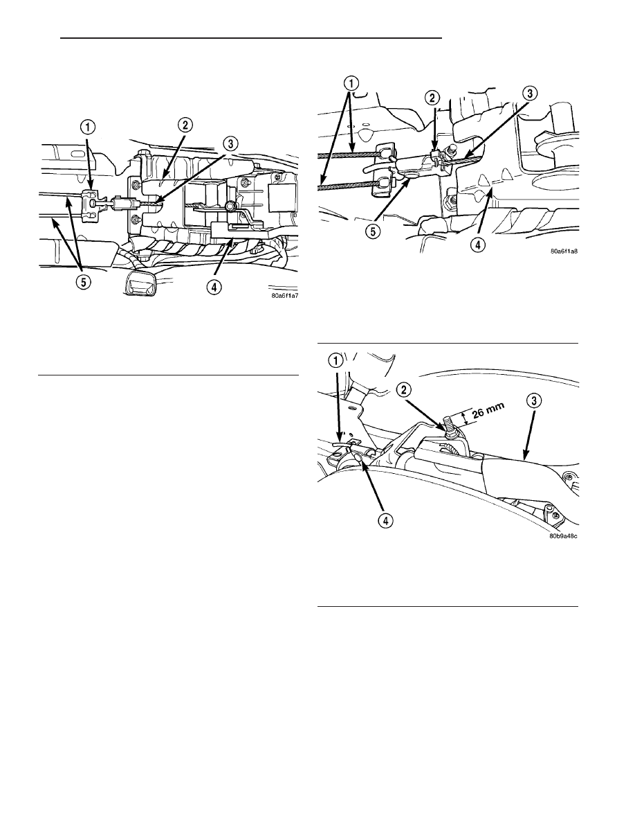
Fig. 88 Park Brake Cable Tension Equalizer

1 - PARK BRAKE CABLE TENSION EQUALIZER
2 - PARK BRAKE MECHANISM
3 - PARK BRAKE LEVER OUTPUT CABLE
4 - PARK BRAKE LEVER
5 - REAR PARK BRAKE CABLES

Fig. 89 Cable Retainer Installed On Tension

Equalizer

1 - REAR PARK BRAKE CABLES
2 - CABLE RETAINING CLIP
3 - PARKING BRAKE MECHANISM OUTPUT CABLE
4 - PARK BRAKE MECHANISM
5 - PARK BRAKE CABLE TENSION EQUALIZER

Fig. 90 Parking Brake Adjustment

1 - BENT NAIL
2 - ADJUSTING NUT
3 - PARKING BRAKE LEVER
4 - PARKING BRAKE CABLE TENSION EQUALIZER

JR

BRAKES - BASE

5 - 47

LEVER - PARKING BRAKE (Continued)

SHOES - PARKING BRAKE

REMOVAL

(1) Remove disc brake caliper from adapter and

rotor (See Disc Brake Shoe Removal).

(2) Remove rotor from hub/bearing.
(3) Remove dust cap from hub/bearing.
(4) Remove hub/bearing rear retaining nut and

washer.

(5) Remove hub/bearing from knuckle.
(6) Remove hold down clip from rear park brake

shoe (Fig. 91).

(7) Turn park brake shoe adjuster wheel until

adjuster is at its shortest length.

(8) Remove the park brake shoe adjuster from the

park brake shoes (Fig. 92).

(9) Remove the lower return spring (Fig. 93)

between the park brake shoes.

Fig. 91 Rear Park Brake Shoe Hold-Down Clip

1 - HOLD DOWN CLIP

Fig. 92 Park Brake Shoe Adjuster

1 - ADJUSTER

Fig. 93 Brake Shoe Lower Return Spring

1 - LOWER SPRING

5 - 48

BRAKES - BASE

JR

(10) Pull the rear park brake shoe away from the

caliper adapter (Fig. 94). Remove the upper return
spring (Fig. 94) from between the park brake shoes.

(11) Remove the hold-down clip from the front

park brake shoe (Fig. 95). Then remove front park
brake shoe.

INSTALLATION

(1) Install front brake shoe and hold down clip

(Fig. 95).

(2) Install the rear park brake shoe and the park

brake shoe upper return spring (Fig. 94).

(3) Pull rear brake shoe over anchor block until

properly located on adapter.

(4) Install the park brake lower return spring (Fig.

93).

(5) Install the adjuster between the park brake

shoes. Adjuster must be installed with the star wheel
toward the rear of the vehicle (Fig. 92).

(6) Install hold down clip on rear park brake shoe

(Fig. 91).

(7) Adjust park brake shoes to an outside diameter

of 171 mm (6.75 inch).

(8) Install hub/bearing on knuckle.
(9) Install A NEW hub/bearing retaining nut.

Tighten the hub/ bearing retaining nut to a torque of
250 N·m (185 ft. lbs.).

(10) Install dust cap on hub/bearing.
(11) Install rotor.
(12) Install rear disc brake caliper on adapter (See

Brake Shoe Removal).

(13)

Install wheel and tire.

(14) Tighten wheel stud nuts to 135 N·m (100

ft.lbs.).

Fig. 94 Brake Shoe and Upper Spring

1 - UPPER SPRING
2 - HOLD DOWN CLIP
3 - REAR PARKING BRAKE SHOE

Fig. 95 Front Park Brake Shoe Hold Down Clip

1 - FRONT BRAKE SHOE ASSEMBLY
2 - HOLD DOWN CLIP

JR

BRAKES - BASE

5 - 49

SHOES - PARKING BRAKE (Continued)

BRAKES - ABS

TABLE OF CONTENTS

page

page

BRAKES - ABS

DESCRIPTION

DESCRIPTION - ANTILOCK BRAKES

. . . . . . 50

DESCRIPTION - ABS PLUS

. . . . . . . . . . . . . . 50

DESCRIPTION - ELECTRONIC VARIABLE

BRAKE PROPORTIONING . . . . . . . . . . . . . . . 50

DESCRIPTION - TRACTION CONTROL

. . . . . 51

OPERATION

OPERATION - ANTILOCK BRAKES

. . . . . . . . 51

OPERATION - ABS PLUS

. . . . . . . . . . . . . . . 52

OPERATION - ELECTRONIC VARIABLE

BRAKE PROPORTIONING . . . . . . . . . . . . . . . 52

OPERATION - TRACTION CONTROL

. . . . . . 52

CAUTION

. . . . . . . . . . . . . . . . . . . . . . . . . . . . . 53

DIAGNOSIS AND TESTING - INSPECTION

AND ROAD TEST

. . . . . . . . . . . . . . . . . . . . . 53

STANDARD PROCEDURE - ANTILOCK BRAKE

SYSTEM BLEEDING

. . . . . . . . . . . . . . . . . . . 54

SPECIFICATIONS

ABS FASTENER TORQUE

. . . . . . . . . . . . . . . 55

TONE WHEEL RUNOUT

. . . . . . . . . . . . . . . . 55

WHEEL SPEED SENSOR AIR GAP

. . . . . . . . 55

FRONT WHEEL SPEED SENSOR

REMOVAL

. . . . . . . . . . . . . . . . . . . . . . . . . . . . . 55

INSTALLATION

. . . . . . . . . . . . . . . . . . . . . . . . . 56

REAR WHEEL SPEED SENSOR

REMOVAL

REMOVAL - JR27

. . . . . . . . . . . . . . . . . . . . . 57

REMOVAL - JR41

. . . . . . . . . . . . . . . . . . . . . 58

INSTALLATION

INSTALLATION - JR27

. . . . . . . . . . . . . . . . . . 59

INSTALLATION - JR41

. . . . . . . . . . . . . . . . . . 59

TONE WHEEL

INSPECTION - TONE WHEEL

. . . . . . . . . . . . . . 59

TRACTION CONTROL SWITCH

REMOVAL

. . . . . . . . . . . . . . . . . . . . . . . . . . . . . 60

INSTALLATION

. . . . . . . . . . . . . . . . . . . . . . . . . 60

HCU (HYDRAULIC CONTROL UNIT)

DESCRIPTION

. . . . . . . . . . . . . . . . . . . . . . . . . 61

OPERATION - HYDRAULIC CIRCUITS AND

VALVES

. . . . . . . . . . . . . . . . . . . . . . . . . . . . . 61

ICU (INTEGRATED CONTROL UNIT)

DESCRIPTION

. . . . . . . . . . . . . . . . . . . . . . . . . 65

OPERATION

. . . . . . . . . . . . . . . . . . . . . . . . . . . 65

REMOVAL

. . . . . . . . . . . . . . . . . . . . . . . . . . . . . 65

DISASSEMBLY

. . . . . . . . . . . . . . . . . . . . . . . . . 67

ASSEMBLY

. . . . . . . . . . . . . . . . . . . . . . . . . . . . 68

INSTALLATION

. . . . . . . . . . . . . . . . . . . . . . . . . 68

BRAKES - ABS

DESCRIPTION

DESCRIPTION - ANTILOCK BRAKES

This section covers the MK25e Antilock Brake Sys-

tem (ABS). This vehicle’s ABS comes standard with
traction control. It is a Brake Traction Control Sys-
tem (BTCS).

The purpose of this four-channel design antilock brake

system is to prevent wheel lockup under braking condi-
tions on virtually any type of road surface. Antilock brak-
ing is desirable because a vehicle that is stopped without
locking the wheels retains directional stability and some
steering capability. This allows the driver to retain
greater control of the vehicle during braking.

This ABS system has ABS Plus and Electronic

Variable Brake Proportioning (EVBP). (Refer to 5 -
ABS - BRAKES - DESCRIPTION)

For information on traction control, (Refer to 5 -

BRAKES - ABS - TRACTION CONTROL - DESCRIP-
TION).

DESCRIPTION - ABS PLUS

There is an ABS Plus function built into the ABS

Antilock Brake Module. ABS Plus is a brake-on sta-
bility enhancement. It is designed to help maintain
the directional stability of the vehicle during braking.
There

are

no

additional

external

components

required for this function.

DESCRIPTION - ELECTRONIC VARIABLE
BRAKE PROPORTIONING

Vehicles equipped with ABS use electronic variable

brake proportioning (EVBP) to balance front-to-rear
braking. The EVBP is used in place of a rear propor-
tioning valve. The EVBP system uses the ABS sys-
tem to control the slip of the rear wheels in partial
braking range. The braking force of the rear wheels
is controlled electronically by using the inlet and out-
let valves located in the integrated control unit
(ICU).

EVBP activation is invisible to the customer since

there is no pump motor noise or brake pedal feed-
back.

5 - 50

BRAKES - ABS

JR


Content   ..  291  292  293  294   ..