Chrysler Sebring, Stratus sedan, Sebring Convertible. Manual - part 287


  Index      Chrysler     Chrysler Sebring, Stratus sedan, Sebring Convertible - service repair manual 2001-2007 year


Search            


Content   ..  285  286  287  288   ..


Chrysler Sebring, Stratus sedan, Sebring Convertible. Manual - part 287


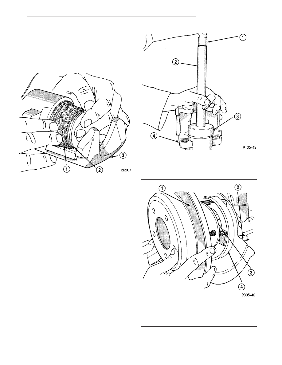
CAUTION: Force applied to the piston to seat it in
the bore must be applied uniformly to avoid cock-
ing and binding of the piston.

(4) Install piston into caliper bore pushing it past

the piston seal until it bottoms in the caliper bore
(Fig. 37).

(5) Position the dust boot into the counterbore of

the caliper assembly piston bore.

(6) Using a hammer and Installer, Special Tool

C-4689 or C-4842 (depending on piston size), and
Handle, Special Tool C-4171, drive the boot into the
counterbore of the caliper as necessary (Fig. 38).

(7) Reinstall the caliper on the vehicle and bleed

the brakes as necessary. Refer to Installation in this
section.

INSTALLATION - REAR DISC BRAKE CALIPER

(1) Completely retract caliper piston back into pis-

ton bore of caliper assembly.

(2) Lubricate both adapter abutments with a lib-

eral amount of Mopar

t Multipurpose Lubricant, or

equivalent.

(3) If removed, install the rotor on the hub making

sure it is squarely seated on the face of the hub (Fig.
39).

CAUTION: Use care when installing caliper assem-
bly onto adapter so the guide pin bushings and
sleeves do not get damaged by the mounting
bosses on adapter.

Fig. 37 Installing Piston Into Caliper Bore

1 - BOOT
2 - PISTON
3 - CALIPER

Fig. 38 Installing Dust Boot

1 - HAMMER
2 - SPECIAL TOOL C-4171
3 - SPECIAL TOOL C-4689 or C-4842
4 - CALIPER

Fig. 39 Installing Rear Rotor

1 - BRAKING DISC
2 - DISC SHIELD
3 - HUB
4 - DRUM-IN-HAT PARKING BRAKE

JR

BRAKES - BASE

5 - 23

DISC BRAKE CALIPER - REAR (Continued)

(4) Carefully lower caliper and brake shoes over

rotor reversing the removal procedure (Fig. 33).
Make sure that the caliper guide pin bolts, bushings
and sleeves are clear of the adapter bosses.

CAUTION: Extreme caution should be taken not to
cross thread the caliper guide pin bolts when they
are installed.

(5) Install the caliper guide pin bolts (Fig. 32).

Tighten the caliper guide pin bolts to a torque of 22
N·m (192 in. lbs.).

(6) Install the brake hose on the caliper. To do

this, first place one NEW special fitting washer on
each side of the hose fitting, then slide the banjo bolt
through the fitting. Next, thread the banjo bolt into
the threaded port on the rear of the brake caliper.
Tighten the banjo bolt to a torque of 35 N·m (26 ft.
lbs.).

(7) Install wheels and tire assembly.
(8) Tighten the wheel mounting stud nuts in

proper sequence until all nuts are torqued to half
specification. Then repeat the tightening sequence to
the full specified torque of 135 N·m (100 ft. lbs.).

(9) Lower vehicle.
(10) Remove the brake pedal depressor (holding)

tool.

(11) Bleed the hydraulic brake circuit to the brake

caliper. (Refer to 5 - BRAKES - STANDARD PROCE-
DURE)

(12) Road test the vehicle and make several stops

to wear off any foreign material on the brakes and to
seat the brake pads.

DRUM

DIAGNOSIS AND TESTING - BRAKE DRUM

OUT-OF-ROUND

A brake drum whose braking surface is out-of-

round can cause vehicle vibration and brake pedal
pulsation upon braking. To measure brake drum out-
of-round, perform the following:

(1) Remove the drum from the vehicle.
(2) Using a brake drum micrometer, measure the

inside diameter at several points around the inside of
the drum on the machined surface. Record the mea-
surements.

Drum

braking

surface

out-of-round

must

not

exceed 0.050 mm (0.002 inch). If the measurement is
not within specification, reface or replace the drum.
(Refer to 5 - BRAKES/HYDRAULIC/MECHANICAL/
DRUM - STANDARD PROCEDURE). Always replace
the drum if machining will cause the diameter to
exceed drum maximum diameter. All brake drums
are marked with the maximum allowable brake
drum diameter (Fig. 40).

RUNOUT

A runout measurement can be done along with the

out-of-round measurement.

(1) Mount the drum on an off-vehicle brake lathe

following the manufacturers instructions.

(2) Mount a dial indicator on the lathe and posi-

tion the indicator needle against center of the brake
drum machined surface.

(3) Slowly rotate the drum by hand recording

high and low indicator readings through a 360° rota-
tion.

Drum braking surface runout must not exceed

0.050 mm (0.002 inch). If the measurement is not
within specification, reface or replace the drum.
(Refer to 5 - BRAKES/HYDRAULIC/MECHANICAL/
DRUM - STANDARD PROCEDURE). Always replace
the drum if machining will cause the diameter to
exceed drum maximum diameter. All brake drums
are marked with the maximum allowable brake
drum diameter (Fig. 40).

STANDARD PROCEDURE - BRAKE DRUM
MACHINING

If a brake drum is deeply scored or warped, it can

be machined on a brake lathe equipped to machine
brake drums. Follow the manufacturers instructions
on the machining procedure.

Measure the brake drum inside diameter before

machining. If machining the drum will cause the
drum to exceed maximum allowable diameter, do not
machine the brake drum. It needs to be replaced.

CAUTION: Do not machine the brake drum if it will
cause the drum to exceed maximum allowable
diameter.

All brake drums are marked with the maximum

allowable brake drum inside diameter (Fig. 40).

When machining, make sure the final finish feed

cut is set to fine in order to avoid a screw effect on
the brake shoes when the brakes are applied. This
final feed cut specification varies from lathe manu-
facturer to lathe manufacturer.

5 - 24

BRAKES - BASE

JR

DISC BRAKE CALIPER - REAR (Continued)

REMOVAL

NOTE: Before proceeding, (Refer to 5 - BRAKES -
WARNING) (Refer to 5 - BRAKES - CAUTION).

(1) Raise vehicle. (Refer to LUBRICATION &

MAINTENANCE/HOISTING - STANDARD PROCE-
DURE)

(2) Remove rear tire and wheel assembly.
(3) Slide brake drum off mounted wheel studs of

hub and remove from vehicle (Fig. 41). If drum does
not come off, further brake clearance can be obtained
by backing off brake adjuster screw using following
steps:

(a) Fabricate pawl release tool like one shown

using a coat hanger or heavy mechanics wire (Fig.
42).

(b) Remove plug from rear of support plate

below wheel cylinder.

(c) Insert fabricated tool through access hole in

support plate, under adjuster, against lever pawl
(Fig. 43). Pawl is attached to and pivots from lead-
ing shoe. When inserting tool through hole, direct-
ing tool somewhat forward (toward leading shoe)
assures better contact with pawl.

(d) While pushing on pawl with fabricated tool

to disengage it from adjuster star-wheel teeth (Fig.
43), rotate star-wheel downward to back off adjust-
ment using a small screwdriver or brake adjuster
tool.

(e) Once adjuster screw is backed off a sufficient

amount, drum should slide off wheel studs.

(f) Remove tools and reinstall plug in support

plate.

INSTALLATION

NOTE: Before installing drum, inspect brake shoe
linings for wear, alignment, and contamination.
Repair or replace as necessary.

NOTE: If rust or any foreign material is present on
hub, drum or wheel mating surfaces, wet wire brush
these areas to remove prior to assembly of parts.

(1) Properly remove any buildup formed along

outer edge of drum’s machined braking surface.

(2) Adjust brake shoes to drum diameter using a

brake shoe gauge. (Refer to 5 - BRAKES/HYDRAU-

Fig. 40 Drum Maximum Diameter Identification

1 - MAXIMUM DIAMETER IDENTIFICATION
230.6 MM (9.079 IN.)
2 - BRAKE DRUM

Fig. 41 Drum Brakes

1 - DUST CAP
2 - NUT
3 - DRUM
4 - HUB AND BEARING
5 - WHEEL CYLINDER
6 - SUPPORT PLATE
7 - BRAKE SHOES

Fig. 42 Fabricated Tool

1 - APPROXIMATELY 15 CM (6 INCHES)
2 - THIS END TO BE INSERTED INTO BRAKE ASSEMBLY

JR

BRAKES - BASE

5 - 25

DRUM (Continued)

LIC/MECHANICAL/BRAKE

PADS/SHOES

-

ADJUSTMENTS)

(3) Install brake drum on rear hub and bearing

(Fig. 41).

(4) Install tire and wheel assembly. Tighten wheel

mounting nuts to 135 N·m (100 ft. lbs.) torque.

(5) Lower vehicle.
(6) Road test vehicle stopping in both forward and

reverse directions. Automatic-adjuster will continue
to adjust brakes as necessary during road test.

FLUID

DIAGNOSIS AND TESTING - BRAKE FLUID
CONTAMINATION

Indications of fluid contamination are swollen or

deteriorated rubber parts.

Swollen rubber parts indicate the presence of

petroleum in the brake fluid.

To test for contamination, put a small amount of

drained brake fluid in clear glass jar. If fluid sepa-
rates into layers, there is mineral oil or other fluid
contamination of the brake fluid.

If brake fluid is contaminated, drain and thor-

oughly flush system. Replace master cylinder, propor-
tioning valve, caliper seals, wheel cylinder seals,
Antilock Brakes hydraulic unit and all hydraulic
fluid hoses.

STANDARD PROCEDURE - BRAKE FLUID
LEVEL CHECKING

Brake fluid level should be checked a minimum of

twice a year.

Master cylinder reservoirs are marked, FULL and

MIN, indicating the allowable brake fluid level range
in the master cylinder brake fluid reservoir.

CAUTION: Use only Mopar

T

brake fluid or an equiv-

alent from a tightly sealed container. Brake fluid
must conform to DOT 3 specifications. Do not use
petroleum-based fluid because seal damage in the
brake system will result.

Although there is a range, the preferred level is

FULL. If necessary, adjust the brake fluid level,
bringing it to the FULL mark on the side of the mas-
ter cylinder brake fluid reservoir.

SPECIFICATIONS

BRAKE FLUID

The brake fluid used in this vehicle must conform

to DOT 3 specifications and SAE J1703 standards.
No other type of brake fluid is recommended or
approved for usage in the vehicle brake system. Use
only Mopar brake fluid or an equivalent from a
tightly sealed container.

CAUTION: Never use reclaimed brake fluid or fluid
from an container which has been left open. An
open container will absorb moisture from the air
and contaminate the fluid.

CAUTION: Never use any type of a petroleum-based
fluid in the brake hydraulic system. Use of such
type fluids will result in seal damage of the vehicle
brake hydraulic system causing a failure of the
vehicle brake system. Petroleum based fluids would
be items such as engine oil, transmission fluid,
power steering fluid, etc.

JUNCTION BLOCK

DESCRIPTION

A junction block is used on vehicles that are not

equipped with antilock brakes (ABS). The junction
block is located on the left side of the lower radiator
support (Fig. 44). The junction block mounts in the
same location as the ABS integrated control unit
(ICU) does on vehicles with ABS.

It has six threaded ports to which the brake tubes

connect. Two are for the brake tubes coming from the
master cylinder. The remaining four ports are for the
brake tubes going to each brake assembly. The valve
is permanently mounted to a bracket which fastens
to the lower radiator support.

Fig. 43 Fabricated Tool Inserted Against Pawl

1 - ACCESS HOLE
2 - STAR WHEEL
3 - LEVER PAWL
4 - FABRICATED TOOL

5 - 26

BRAKES - BASE

JR

DRUM (Continued)


Content   ..  285  286  287  288   ..