Chrysler Sebring, Stratus sedan, Sebring Convertible. Manual - part 283


  Index      Chrysler     Chrysler Sebring, Stratus sedan, Sebring Convertible - service repair manual 2001-2007 year


Search            


Content   ..  281  282  283  284   ..


Chrysler Sebring, Stratus sedan, Sebring Convertible. Manual - part 283


hydraulic brake hoses for surface cracking, scuffing,
or worn spots. If the fabric casing of the rubber hose
becomes exposed due to cracks or abrasions in the
rubber hose cover, the hose should be replaced imme-
diately. Eventual deterioration of the hose can take
place with possible burst failure. Faulty installation
can cause twisting, resulting in wheel, tire, or chassis
interference.

The brake tubing should be inspected periodically

for evidence of physical damage or contact with mov-
ing or hot components.

The flexible brake tube sections used on this vehicle

in the primary and secondary tubes from the master
cylinder to the ABS hydraulic control unit connections
must also be inspected. This flexible tubing must be
inspected for kinks, fraying and contact with other com-
ponents or with the body of the vehicle.

BRAKE PADS/SHOES - FRONT

REMOVAL - FRONT DISC BRAKE SHOES

(1) Raise the vehicle. (Refer to LUBRICATION &

MAINTENANCE/HOISTING - STANDARD PROCE-
DURE).

(2) Remove both front wheel and tire assemblies.

NOTE: Using this procedure, begin on one side of
the vehicle.

(3) Remove the anti-rattle spring from the out-

board side of the caliper and adapter (Fig. 4).

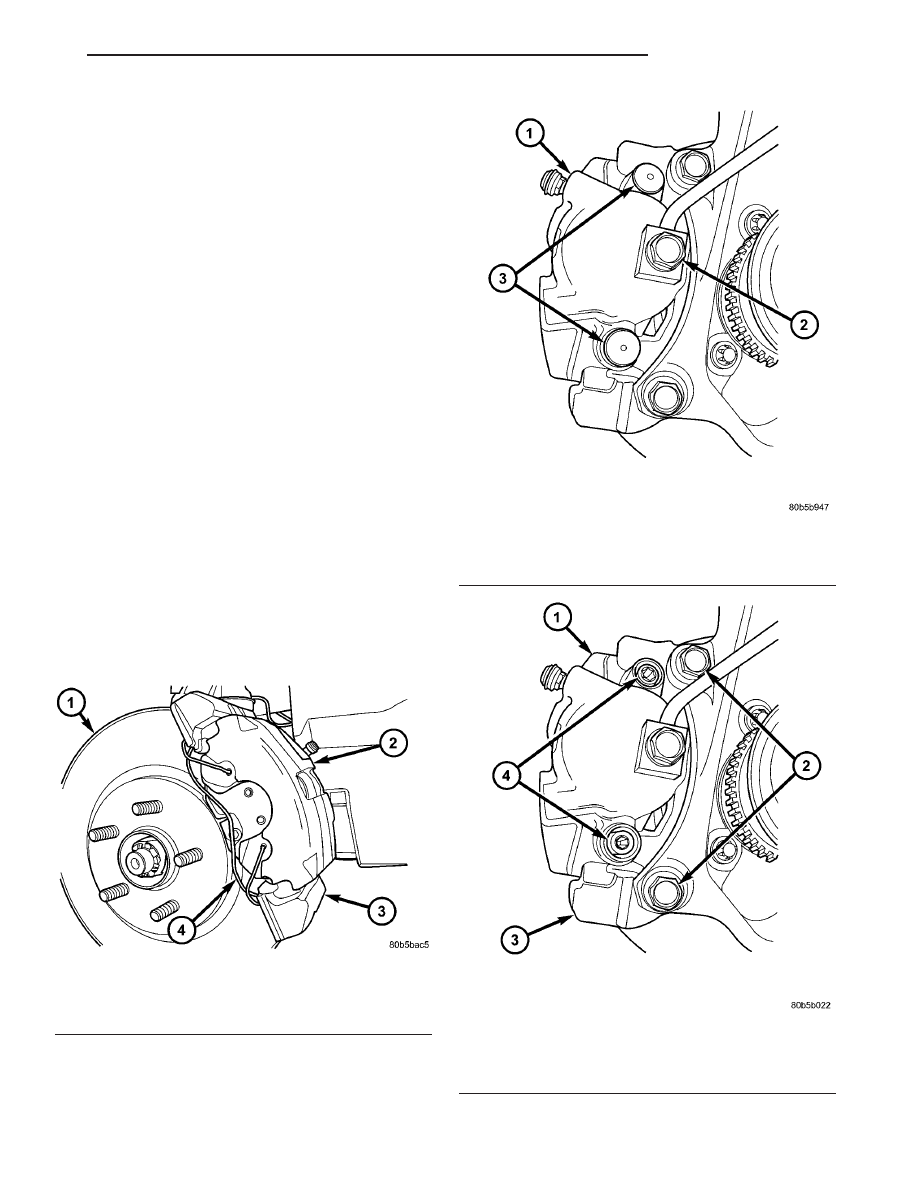
(4) Remove the two caps in place over the caliper

guide pin bolts (Fig. 5).

(5) Remove the two caliper guide pin bolts (Fig. 6).

Fig. 4 FRONT DISC BRAKES

1 - BRAKE ROTOR
2 - BRAKE CALIPER
3 - BRAKE CALIPER ADAPTER
4 - ANTI-RATTLE SPRING

Fig. 5 CALIPER GUIDE PIN BOLT CAPS

1 - FRONT BRAKE CALIPER
2 - BRAKE HOSE BANJO BOLT
3 - CAPS

Fig. 6 CALIPER MOUNTING

1 - FRONT BRAKE CALIPER
2 - CALIPER ADAPTER MOUNTING BOLTS
3 - CALIPER ADAPTER
4 - CALIPER GUIDE PIN BOLTS

JR

BRAKES - BASE

5 - 7

BRAKE LINES (Continued)

(6) Remove caliper from caliper adapter and brake

rotor. The outboard shoe will probably stay with the
caliper adapter while the inboard shoe will come off
with the caliper as the caliper is removed.

CAUTION: Supporting weight of caliper by the flex-
ible brake fluid hose can damage the hose.

(7) Using wire or cord, hang the caliper from the

front strut assembly (Fig. 7). Support the caliper
firmly to prevent weight of caliper from being sup-
ported by the brake fluid hose.

(8) Remove the outboard brake shoe from the cali-

per adapter.

(9) Pull the inboard brake shoe away from the cal-

iper piston until the retaining clip on shoe is free
from the cavity in the caliper piston (Fig. 8).

(10) Repeat the above procedure on other side of

the vehicle.

CLEANING - DISC BRAKE SHOES

WARNING: DUST AND DIRT ACCUMULATING ON
BRAKE PARTS DURING NORMAL USE MAY CON-
TAIN ASBESTOS FIBERS FROM PRODUCTION OR
AFTERMARKET

BRAKE

LININGS.

BREATHING

EXCESSIVE

CONCENTRATIONS

OF

ASBESTOS

FIBERS CAN CAUSE SERIOUS BODILY HARM.
EXERCISE

CARE

WHEN

SERVICING

BRAKE

PARTS. DO NOT SAND OR GRIND BRAKE LINING
UNLESS EQUIPMENT USED IS DESIGNED TO CON-
TAIN THE DUST RESIDUE. DO NOT CLEAN BRAKE
PARTS

WITH

COMPRESSED AIR

OR

BY DRY

BRUSHING. CLEANING SHOULD BE DONE BY
DAMPENING THE BRAKE COMPONENTS WITH A

FINE MIST OF WATER, THEN WIPING THE BRAKE
COMPONENTS CLEAN WITH A DAMPENED CLOTH.
DISPOSE OF CLOTH AND ALL RESIDUE CONTAIN-
ING ASBESTOS FIBERS IN AN IMPERMEABLE
CONTAINER WITH THE APPROPRIATE LABEL. FOL-
LOW PRACTICES PRESCRIBED BY THE OCCUPA-
TIONAL SAFETY AND HEALTH ADMINISTRATION
(OSHA) AND THE ENVIRONMENTAL PROTECTION
AGENCY (EPA) FOR THE HANDLING, PROCESSING,
AND DISPOSING OF DUST OR DEBRIS THAT MAY
CONTAIN ASBESTOS FIBERS.

INSPECTION - DISC BRAKE SHOES

Visually inspect brake shoes (pads) for uneven lin-

ing wear. Also inspect for excessive lining deteriora-
tion. Check the clearance between the tips of the
wear indicators on the shoes (if equipped) and the
brake rotors.

If a visual inspection does not adequately deter-

mine the condition of the lining, a physical check will
be necessary. To check the amount of lining wear,
remove the disc brake shoes from the calipers.

Measure each brake shoe. The combined brake

shoe and its lining material thickness should be mea-
sured at its thinnest point.

• For front disc brake shoes, when a set of brake

shoes are worn to a thickness of approximately 7.0
mm (9/32 inch), they should be replaced.

• For rear disc brake shoes, when a set of brake

shoes are worn to a thickness of approximately 7.0
mm (9/32 inch), they should be replaced.

• Typically, if front shoes are worn out, both fronts

and rears need to be replaced. Make sure to check
rears.

Fig. 7 Stored Front Disc Brake Caliper

1 - STEERING KNUCKLE
2 - BRAKE FLEX HOSE
3 - CALIPER ASSEMBLY
4 - WIRE HANGER
5 - STRUT ASSEMBLY

Fig. 8 Removing Inboard Shoe

1 - INBOARD BRAKE SHOE
2 - HANGER WIRE
3 - CALIPER ASSEMBLY
4 - RETAINING CLIP
5 - PISTON

5 - 8

BRAKES - BASE

JR

BRAKE PADS/SHOES - FRONT (Continued)

Replace both disc brake shoes (inboard and out-

board) on each caliper. It is necessary to replace the
shoes on the opposite side of the vehicle as well as
the shoes failing inspection.

If the brake shoe assemblies do not require

replacement, be sure to reinstall the brake shoes in
the original position they were remove from.

INSTALLATION - FRONT DISC BRAKE SHOES

NOTE: There may be more than 1 lining material
released.

Make

sure

proper

linings

are

being

installed.

(1) Begin on one side of the vehicle or the other.
(2) Completely retract the caliper piston back into

its bore in the brake caliper (This is required for cal-
iper installation on the brake rotor with new brake
shoes installed).

(3) If applied, remove the protective paper from

the noise suppression gasket on the rear of both the
inner and outer brake shoe assemblies.

NOTE: Inboard brake shoes are stamped L or R for
left or right side of the vehicle. The P-slot or void
on piston insulator must be positioned upward
when brake caliper is mounted (Fig. 9).

(4) Install the new inboard brake shoe into the cal-

iper piston by firmly pressing its retaining clip into
the piston bore. Be sure the inboard brake shoe is
positioned squarely against the face of the caliper
piston.

(5) Lubricate both adapter abutments where the

shoes slide with a small amount of Mopar

t Dielectric

grease, or equivalent.

(6) Slide the new outboard brake shoe into the cal-

iper adapter with the lining up against the outside of
the brake rotor.

CAUTION: Use care when installing the caliper
assembly onto the caliper adapter, so the caliper
guide pin bushings do not get damaged by the
adapter bosses.

(7) Carefully position the brake caliper over the

brake rotor and adapter.

(8) Install the caliper guide pin bolts and tighten

to a torque of 35 N·m (26 ft. lbs.). Extreme caution
should be taken not to cross thread the caliper
guide pin bolts.

(9) Install the caps over the caliper guide pin bolts

(Fig. 5).

(10) Install the new caliper hold down spring (anti-

rattle clip) on the outboard side of the caliper. Start
the spring into the holes on the caliper, then stretch
the clip legs past the abutments on the caliper
adapter (Fig. 4).

(11) Repeat the above procedure on other side of

the vehicle.

(12) Install the wheel and tire assemblies. Tighten

the wheel mounting nuts in proper sequence until all
nuts are torqued to half specification, then repeat the
tightening sequence to the full specified torque of 135
N·m (100 ft. lbs.).

(13) Lower vehicle.
(14) Pump the brake pedal several times. This will

set the shoes to the brake rotor.

(15) Check and adjust brake fluid level as neces-

sary.

(16) Road test the vehicle and make several stops

to wear off any foreign material on the brakes and to
seat the brake shoes.

BRAKE PADS/SHOES - REAR
DISC

REMOVAL - REAR DISC BRAKE SHOES

(1) Raise vehicle. (Refer to LUBRICATION &

MAINTENANCE/HOISTING - STANDARD PROCE-
DURE)

(2) Remove rear wheels and tires from vehicle.

Fig. 9 INBOARD SHOE ORIENTATION TO TURNING

ROTOR

1 - P-SLOT/VOID
2 - INBOARD DISC BRAKE SHOE/PAD

JR

BRAKES - BASE

5 - 9

BRAKE PADS/SHOES - FRONT (Continued)

(3) Remove the 2 guide pin bolts mounting the cal-

iper to the adapter (Fig. 10).

(4) Remove caliper from adapter and rotor by first

rotating the top of the caliper away from adapter,
and then lifting the caliper off the lower machined
abutment on adapter (Fig. 11).

(5) Support caliper from rear strut to prevent

weight of caliper from damaging the flexible brake
hose (Fig. 12).

(6) Remove rear rotor from hub/bearing (Fig. 13).

Then inspect drum-in-hat parking brake shoes and
parking brake braking surface on rotor for any signs
of excessive wear or damage. Replace parking brake
shoes if required.

(7) Remove outboard brake pad from caliper by

prying brake pad retaining clip over raised area on

Fig. 10 Caliper Guide Pin Bolts

1 - DISC BRAKE CALIPER
2 - CALIPER GUIDE PIN BOLTS

Fig. 11 Caliper Removal/Installation

1 - BRAKING DISC
2 - CALIPER ADAPTER
3 - CALIPER
4 - LOWER MACHINED ADAPTER ABUTMENT

Fig. 12 Storing Caliper

1 - FLEX HOSE
2 - STRUT
3 - WIRE HANGER
4 - CALIPER ASSEMBLY

Fig. 13 Rear Brake Rotor

1 - BRAKING DISC
2 - DISC SHIELD
3 - HUB
4 - DRUM-IN-HAT PARKING BRAKE

5 - 10

BRAKES - BASE

JR

BRAKE PADS/SHOES - REAR DISC (Continued)


Content   ..  281  282  283  284   ..