Chrysler Sebring, Stratus sedan, Sebring Convertible. Manual - part 281


  Index      Chrysler     Chrysler Sebring, Stratus sedan, Sebring Convertible - service repair manual 2001-2007 year


Search            


Content   ..  279  280  281  282   ..


Chrysler Sebring, Stratus sedan, Sebring Convertible. Manual - part 281


(5) Slide failed sealing boot off interconnecting

shaft.

(6) Thoroughly clean and inspect outer C/V joint

assembly and interconnecting joint for any signs of
excessive wear. If any parts show signs of exces-
sive wear, the driveshaft assembly will require
replacement. Component parts of these drive-
shaft assemblies are not serviceable.

INSTALLATION

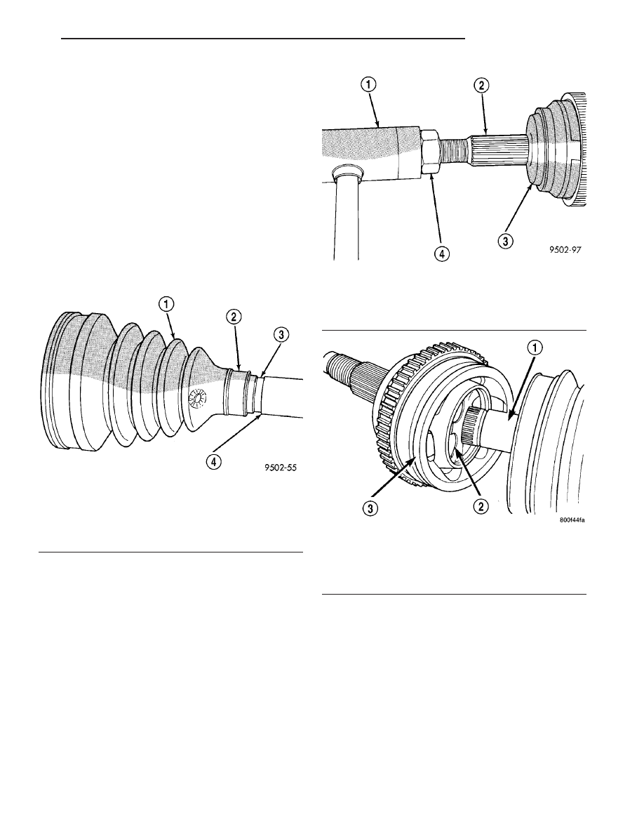
(1) Slide new sealing boot to interconnecting shaft

retaining clamp onto interconnecting shaft. Slide the
outer C/V joint assembly sealing boot onto the inter-
connecting shaft (Fig. 40). Seal boot MUST be
positioned on interconnecting shaft so the
raised bead on the inside of the seal boot is in
groove on interconnecting shaft.

(2) Align splines on interconnecting shaft with

splines on cross of outer C/V joint assembly and start
outer C/V joint onto interconnecting shaft.

(3) Install outer C/V joint assembly onto intercon-

necting shaft by using a soft–faced hammer and
tapping end of stub axle (with nut installed) until
outer C/V joint is fully seated on interconnecting
shaft (Fig. 41).

(4) Outer C/V joint assembly must be installed on

interconnecting shaft until cross of outer C/V joint
assembly is seated against circlip on interconnecting
shaft (Fig. 42).

(5) Distribute 1/2 the amount of grease provided in

seal boot service package (DO NOT USE ANY
OTHER TYPE OF GREASE) into outer C/V joint
assembly housing. Put the remaining amount into
the sealing boot.

Fig. 40 Sealing Boot Installation on Interconnecting

Shaft

1 - SEALING BOOT
2 - RAISED BEAD IN THIS AREA OF SEALING BOOT
3 - GROOVE
4 - INTERCONNECTING SHAFT

Fig. 41 Outer C/V

1 - SOFT FACED HAMMER
2 - STUB AXLE
3 - OUTER C/V JOINT
4 - NUT

Fig. 42 Outer C/V Joint Correctly Installed on

Interconnecting Shaft

1 - INTERCONNECTING SHAFT
2 - CROSS
3 - OUTER C/V JOINT ASSEMBLY

JR

HALF SHAFT

3 - 15

CV BOOT - OUTER (Continued)

(6) Install outer C/V joint sealing boot to intercon-

necting shaft clamp evenly on sealing boot.

(7) Clamp sealing boot onto interconnecting shaft

using crimper, Special Tool C-4975-A and the follow-
ing procedure. Place crimping tool C-4975-A over
bridge of clamp (Fig. 43). Tighten nut on crimping
tool C-4975-A until jaws on tool are closed completely
together, face to face (Fig. 44).

CAUTION: Seal must not be dimpled, stretched, or
out–of–shape in any way. If seal is NOT shaped cor-
rectly, equalize pressure in seal and shape it by
hand.

(8) Position outer C/V joint sealing boot into its

retaining groove on outer C/V joint housing. Install
sealing boot to outer C/V joint retaining clamp evenly
on sealing boot.

(9) Clamp sealing boot onto outer C/V joint hous-

ing using Crimper, Special Tool C-4975-A and the fol-
lowing procedure. Place crimping tool C-4975-A over
bridge of clamp (Fig. 45). Tighten nut on crimping
tool C-4975-A until jaws on tool are closed completely
together, face to face (Fig. 46).

Fig. 43 Crimping Tool Installed on Sealing Boot

Clamp

1 - SPECIAL TOOL C-4975A
2 - INTERCONNECTING SHAFT
3 - CLAMP
4 - SEALING BOOT

Fig. 44 Sealing Boot Retaining Clamp Installed

1 - CLAMP
2 - JAWS OF SPECIAL TOOL C-4975A MUST BE CLOSED
COMPLETELY TOGETHER HERE
3 - INTERCONNECTING SHAFT
4 - SEALING BOOT

Fig. 45 Crimping Tool Installed on Sealing Boot

Clamp

1 - CLAMP
2 - TRIPOD JOINT HOUSING
3 - SPECIAL TOOL C-4975A
4 - SEALING BOOT

Fig. 46 Sealing Boot Retaining Clamp Installed

1 - CLAMP
2 - TRIPOD HOUSING
3 - SPECIAL TOOL C-4975A
4 - JAWS OF SPECIAL TOOL C-4975A MUST BE CLOSED
COMPLETELY TOGETHER HERE
5 - SEALING BOOT

3 - 16

HALF SHAFT

JR

CV BOOT - OUTER (Continued)

BRAKES

TABLE OF CONTENTS

page

page

BRAKES - BASE . . . . . . . . . . . . . . . . . . . . . . . . . . . 1

BRAKES - ABS . . . . . . . . . . . . . . . . . . . . . . . . . . . 50

BRAKES - BASE

TABLE OF CONTENTS

page

page

BRAKES - BASE

WARNING

. . . . . . . . . . . . . . . . . . . . . . . . . . . . . 2

CAUTION

. . . . . . . . . . . . . . . . . . . . . . . . . . . . . . 2

STANDARD PROCEDURE - BASE BRAKE

BLEEDING

. . . . . . . . . . . . . . . . . . . . . . . . . . . . 3

SPECIFICATIONS

BRAKE FASTENER TORQUE

. . . . . . . . . . . . . 4

SPECIAL TOOLS

BASE BRAKE SYSTEM

. . . . . . . . . . . . . . . . . . 5

BRAKE FLUID LEVEL SWITCH

REMOVAL

. . . . . . . . . . . . . . . . . . . . . . . . . . . . . 6

INSTALLATION

. . . . . . . . . . . . . . . . . . . . . . . . . . 6

ASPIRATOR VALVE

DESCRIPTION

. . . . . . . . . . . . . . . . . . . . . . . . . . 6

OPERATION

. . . . . . . . . . . . . . . . . . . . . . . . . . . . 6

REMOVAL

. . . . . . . . . . . . . . . . . . . . . . . . . . . . . 6

INSTALLATION

. . . . . . . . . . . . . . . . . . . . . . . . . . 6

BRAKE LINES

DESCRIPTION - BRAKE TUBES AND HOSES

. . 6

OPERATION - BRAKE TUBES AND HOSES

. . . . 6

INSPECTION - BRAKE TUBES AND HOSES

. . . . 6

BRAKE PADS/SHOES - FRONT

REMOVAL - FRONT DISC BRAKE SHOES

. . . . . 7

CLEANING - DISC BRAKE SHOES

. . . . . . . . . . . 8

INSPECTION - DISC BRAKE SHOES

. . . . . . . . . 8

INSTALLATION - FRONT DISC BRAKE SHOES

. 9

BRAKE PADS/SHOES - REAR DISC

REMOVAL - REAR DISC BRAKE SHOES

. . . . . . 9

CLEANING - DISC BRAKE SHOES

. . . . . . . . . . 11

INSPECTION - DISC BRAKE SHOES

. . . . . . . . 11

INSTALLATION - REAR DISC BRAKE SHOES

. . 12

BRAKE PADS/SHOES - REAR DRUM

REMOVAL

. . . . . . . . . . . . . . . . . . . . . . . . . . . . . 12

CLEANING

. . . . . . . . . . . . . . . . . . . . . . . . . . . . 13

INSPECTION

. . . . . . . . . . . . . . . . . . . . . . . . . . 14

INSTALLATION

. . . . . . . . . . . . . . . . . . . . . . . . . 14

ADJUSTMENTS

ADJUSTMENT - DRUM BRAKE SHOES

. . . . 14

DISC BRAKE CALIPER - FRONT

REMOVAL - FRONT DISC BRAKE CALIPER

. . . 15

DISASSEMBLY

DISASSEMBLY - CALIPER GUIDE PIN

BUSHINGS (DISC/DISC BRAKES) . . . . . . . . . 16

DISASSEMBLY - CALIPER PISTON AND

SEAL . . . . . . . . . . . . . . . . . . . . . . . . . . . . . . . 16

CLEANING - CALIPER

. . . . . . . . . . . . . . . . . . . 17

INSPECTION - CALIPER

. . . . . . . . . . . . . . . . . . 18

ASSEMBLY

ASSEMBLY - CALIPER GUIDE PIN

BUSHINGS (DISC/DISC BRAKES) . . . . . . . . . 18

ASSEMBLY - CALIPER PISTON AND SEAL

. . 18

INSTALLATION - FRONT DISC BRAKE

CALIPER

. . . . . . . . . . . . . . . . . . . . . . . . . . . . 19

DISC BRAKE CALIPER - REAR

REMOVAL - REAR DISC BRAKE CALIPER

. . . . 20

DISASSEMBLY

DISASSEMBLY - CALIPER GUIDE PIN

BUSHINGS (DISC/DISC BRAKES) . . . . . . . . . 20

DISASSEMBLY - CALIPER PISTON AND

SEAL . . . . . . . . . . . . . . . . . . . . . . . . . . . . . . . 20

CLEANING - CALIPER

. . . . . . . . . . . . . . . . . . . 22

INSPECTION - CALIPER

. . . . . . . . . . . . . . . . . . 22

ASSEMBLY

ASSEMBLY - CALIPER GUIDE PIN

BUSHINGS (DISC/DISC BRAKES) . . . . . . . . . 22

ASSEMBLY - CALIPER PISTON

AND SEAL . . . . . . . . . . . . . . . . . . . . . . . . . . . 22

INSTALLATION - REAR DISC BRAKE CALIPER

. 23

DRUM

DIAGNOSIS AND TESTING - BRAKE DRUM

. . . 24

STANDARD PROCEDURE - BRAKE DRUM

MACHINING

. . . . . . . . . . . . . . . . . . . . . . . . . . 24

REMOVAL

. . . . . . . . . . . . . . . . . . . . . . . . . . . . . 25

INSTALLATION

. . . . . . . . . . . . . . . . . . . . . . . . . 25

JR

BRAKES

5 - 1

FLUID

DIAGNOSIS AND TESTING - BRAKE FLUID

CONTAMINATION

. . . . . . . . . . . . . . . . . . . . . 26

STANDARD PROCEDURE - BRAKE FLUID

LEVEL CHECKING

. . . . . . . . . . . . . . . . . . . . . 26

SPECIFICATIONS

BRAKE FLUID

. . . . . . . . . . . . . . . . . . . . . . . . 26

JUNCTION BLOCK

DESCRIPTION

. . . . . . . . . . . . . . . . . . . . . . . . . 26

OPERATION

. . . . . . . . . . . . . . . . . . . . . . . . . . . 27

REMOVAL

. . . . . . . . . . . . . . . . . . . . . . . . . . . . . 27

INSTALLATION

. . . . . . . . . . . . . . . . . . . . . . . . . 28

MASTER CYLINDER

STANDARD PROCEDURE - MASTER

CYLINDER BLEEDING

. . . . . . . . . . . . . . . . . . 28

REMOVAL

. . . . . . . . . . . . . . . . . . . . . . . . . . . . . 28

INSTALLATION

. . . . . . . . . . . . . . . . . . . . . . . . . 29

POWER BRAKE BOOSTER

DIAGNOSIS AND TESTING - POWER BRAKE

BOOSTER

. . . . . . . . . . . . . . . . . . . . . . . . . . . 29

REMOVAL - POWER BRAKE BOOSTER

. . . . . . 29

INSTALLATION - POWER BRAKE BOOSTER

. . 31

PROPORTIONING VALVE

DESCRIPTION

. . . . . . . . . . . . . . . . . . . . . . . . . 31

OPERATION

. . . . . . . . . . . . . . . . . . . . . . . . . . . 31

DIAGNOSIS AND TESTING -

PROPORTIONING VALVE

. . . . . . . . . . . . . . . 31

ROTOR

DIAGNOSIS AND TESTING - BRAKE ROTOR

. . 33

STANDARD PROCEDURE - BRAKE ROTOR

MACHINING

. . . . . . . . . . . . . . . . . . . . . . . . . . 35

REMOVAL

REMOVAL - FRONT ROTOR

. . . . . . . . . . . . . 36

REMOVAL - REAR ROTOR

. . . . . . . . . . . . . . 37

INSTALLATION

INSTALLATION - FRONT ROTOR

. . . . . . . . . 37

INSTALLATION - REAR ROTOR

. . . . . . . . . . 37

SUPPORT PLATE

REMOVAL

. . . . . . . . . . . . . . . . . . . . . . . . . . . . . 37

INSTALLATION

. . . . . . . . . . . . . . . . . . . . . . . . . 38

WHEEL CYLINDER

REMOVAL

. . . . . . . . . . . . . . . . . . . . . . . . . . . . . 38

INSTALLATION

. . . . . . . . . . . . . . . . . . . . . . . . . 39

PARKING BRAKE

ADJUSTMENTS

ADJUSTMENT - PARKING BRAKE

. . . . . . . . 39

CABLES - PARKING BRAKE

REMOVAL

. . . . . . . . . . . . . . . . . . . . . . . . . . . . . 41

INSTALLATION

. . . . . . . . . . . . . . . . . . . . . . . . . 43

LEVER - PARKING BRAKE

REMOVAL

. . . . . . . . . . . . . . . . . . . . . . . . . . . . . 46

INSTALLATION

. . . . . . . . . . . . . . . . . . . . . . . . . 46

SHOES - PARKING BRAKE

REMOVAL

. . . . . . . . . . . . . . . . . . . . . . . . . . . . . 48

INSTALLATION

. . . . . . . . . . . . . . . . . . . . . . . . . 49

BRAKES - BASE

WARNING

WARNING: DUST AND DIRT ACCUMULATING ON
BRAKE PARTS DURING NORMAL USE MAY CON-
TAIN ASBESTOS FIBERS FROM PRODUCTION OR
AFTERMARKET

BRAKE

LININGS.

BREATHING

EXCESSIVE

CONCENTRATIONS

OF

ASBESTOS

FIBERS CAN CAUSE SERIOUS BODILY HARM.
EXERCISE

CARE

WHEN

SERVICING

BRAKE

PARTS. DO NOT SAND OR GRIND BRAKE LINING
UNLESS EQUIPMENT USED IS DESIGNED TO CON-
TAIN THE DUST RESIDUE. DO NOT CLEAN BRAKE
PARTS

WITH

COMPRESSED AIR

OR

BY DRY

BRUSHING. CLEANING SHOULD BE DONE BY
DAMPENING THE BRAKE COMPONENTS WITH A
FINE MIST OF WATER, THEN WIPING THE BRAKE
COMPONENTS CLEAN WITH A DAMPENED CLOTH.
DISPOSE OF CLOTH AND ALL RESIDUE CONTAIN-
ING ASBESTOS FIBERS IN AN IMPERMEABLE
CONTAINER WITH THE APPROPRIATE LABEL. FOL-
LOW PRACTICES PRESCRIBED BY THE OCCUPA-
TIONAL SAFETY AND HEALTH ADMINISTRATION
(OSHA) AND THE ENVIRONMENTAL PROTECTION

AGENCY (EPA) FOR THE HANDLING, PROCESSING,
AND DISPOSING OF DUST OR DEBRIS THAT MAY
CONTAIN ASBESTOS FIBERS.

CAUTION

CAUTION: During service procedures, grease or
any other foreign material must be kept off brake
shoes and braking surfaces of brake rotor or drum,
and external surfaces of hub and bearing assembly.

CAUTION: Brake rotor and caliper handling must be
done in such a way as to avoid damage to the rotor,
especially the machined surfaces, and scratching or
nicking of the brake linings.

CAUTION: Only the recommended jacking or hoist-
ing procedures for this vehicle are to be used
whenever it is necessary to lift a vehicle. Failure to
raise a vehicle utilizing the recommended lift points
can result in damage to the vehicle. (Refer to
LUBRICATION & MAINTENANCE/HOISTING - STAN-
DARD PROCEDURE)

5 - 2

BRAKES - BASE

JR


Content   ..  279  280  281  282   ..