Chrysler Sebring, Stratus sedan, Sebring Convertible. Manual - part 279


  Index      Chrysler     Chrysler Sebring, Stratus sedan, Sebring Convertible - service repair manual 2001-2007 year


Search            


Content   ..  277  278  279  280   ..


Chrysler Sebring, Stratus sedan, Sebring Convertible. Manual - part 279


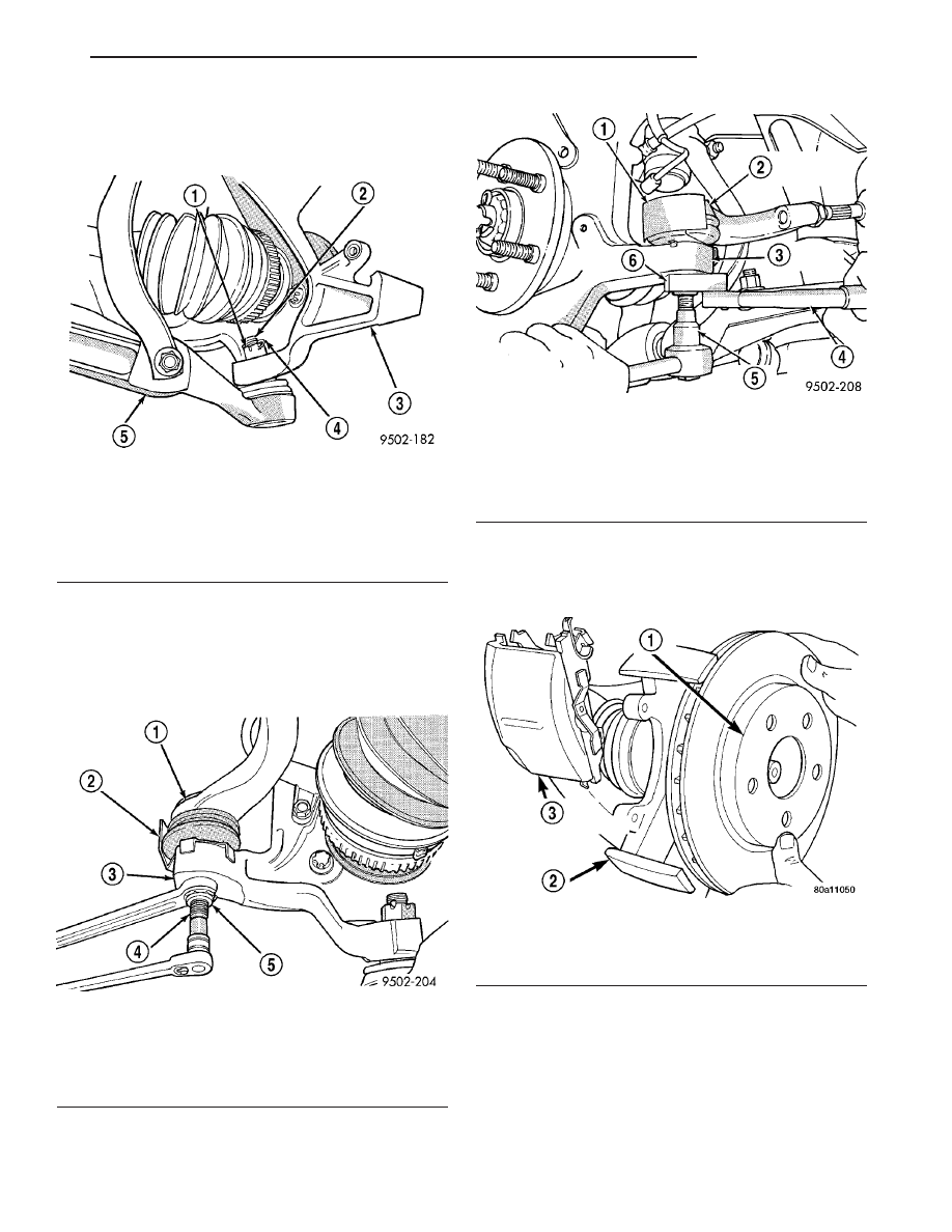
(7) Install the steering knuckle to ball joint stud

castle nut (Fig. 15). Tighten the castle nut to 95 N·m
(70 ft. lbs.).

(8) Install tie rod end into the steering knuckle.

Start tie rod end to steering knuckle nut onto stud of
tie rod end. While holding stud of tie rod end station-
ary (Fig. 16), tighten tie rod end to steering knuckle
nut. Using a crowfoot and 11/32 socket, tighten the
nut to 55 N·m (41 ft. lbs.) (Fig. 17).

(9) Install brake rotor to hub (Fig. 18).
(10) Install caliper/adapter bracket assembly on

steering knuckle. Install and torque caliper adapter-
to-knuckle bolts to 88 N·m (65 ft. lbs.).

Fig. 15 Lower Ball Joint to Steering Knuckle

Attachment

1 - CASTLE NUT
2 - BALL JOINT STUD
3 - STEERING KNUCKLE
4 - COTTER PIN
5 - LOWER CONTROL ARM

Fig. 16 Installing Tie Rod End Nut

1 - TIE ROD
2 - HEAT SHIELD
3 - STEERING KNUCKLE
4 - TIE ROD STUD
5 - NUT

Fig. 17 Torquing Tie Rod End Nut

1 - HEAT SHIELD
2 - OUTER TIE ROD
3 - STEERING KNUCKLE
4 - TORQUE WRENCH
5 - 11/32 SOCKET
6 - CROWFOOT

Fig. 18 Installing Disc Brake Caliper and Rotor

1 - BRAKING DISC
2 - STEERING KNUCKLE
3 - DISC BRAKE CALIPER ASSEMBLY (STORED)

JR

HALF SHAFT

3 - 7

HALF SHAFT (Continued)

(11) Clean all foreign matter from the threads of

the outer C/V joint stub axle. Install hub nut onto
threads of halfshaft (Fig. 19). With vehicle brakes
applied to keep braking disc from turning, tighten
hub nut to 150 N·m (110 ft. lbs.) (Fig. 20).

(12) Install front wheel and tire assembly. Install

front wheel lug nuts and tighten in the correct
sequence (Fig. 21). Tighten lug nuts to 135 N·m (100
ft. lbs.).

(13) Lower vehicle.

Fig. 19 Halfshaft Retaining Nut—Typical

1 - HUB/BEARING ASSEMBLY
2 - NUT

Fig. 20 Torquing Front Hub Nut—Typical

1 - TORQUE WRENCH
2 - HUB
3 - BRAKING DISC

Fig. 21 Wheel Lug Torquing Sequence—Typical

3 - 8

HALF SHAFT

JR

HALF SHAFT (Continued)

SPECIFICATIONS - HALFSHAFT

TORQUE SPECIFICATIONS

DESCRIPTION

N·m

Ft. Lbs.

In. Lbs.

Nut, Ball Joint-to-Knuckle

95

70

Nut, Halfshaft-to-Hub/

Bearing

150

110

Nut, Tie Rod-to-Knuckle

55

41

Nut, Wheel-to-Hub

135

100

SPECIAL TOOLS

HALFSHAFT

CV BOOT - INNER

REMOVAL

(1) Remove large boot clamp which retains inner

tripod joint sealing boot to tripod joint housing and
discard. Remove small clamp which retains inner tri-
pod joint sealing boot to interconnecting shaft and
discard. Remove the sealing boot from the tripod
housing and slide it down the interconnecting shaft.

CAUTION: When removing the tripod joint housing
from the spider assembly, hold the bearings in
place on the spider trunions to prevent the bearings
from falling away.

(2) Slide the tripod joint housing off the spider

assembly and the interconnecting shaft (Fig. 22).

Puller 1026

Boot Clamp Installer C-4975A

Tie Rod Remover MB-991113

Fig. 22 Spider Assembly Removal from Tripod Joint

Housing

1 - TRIPOD JOINT HOUSING
2 - SPIDER ASSEMBLY
3 - SEALING BOOT

JR

HALF SHAFT

3 - 9

HALF SHAFT (Continued)

(3) Remove snap ring which retains spider assem-

bly to interconnecting shaft (Fig. 23). Remove the
spider assembly from interconnecting shaft. If spider
assembly will not come off interconnecting shaft by
hand, it can be removed by tapping spider assembly
with a brass drift (Fig. 24). Do not hit the outer
tripod bearings in an attempt to remove spider
assembly from interconnecting shaft.

(4) Slide sealing boot off interconnecting shaft.
(5) Thoroughly clean and inspect spider assembly,

tripod joint housing, and interconnecting shaft for
any signs of excessive wear. If any parts show
signs of excessive wear, the driveshaft assembly
will require replacement. Component parts of
these driveshaft assemblies are not serviceable.

INSTALLATION

(1) Slide inner tripod joint seal boot retaining

clamp, onto interconnecting shaft. Then, slide the
replacement inner tripod joint sealing boot onto the
interconnecting shaft. Inner tripod joint seal boot
MUST be positioned on interconnecting shaft,
so the raised bead on the inside of the seal boot
is in groove on interconnecting shaft (Fig. 25).

Fig. 23 Spider Assembly Retaining Snap Ring

1 - INTERCONNECTING SHAFT
2 - SPIDER ASSEMBLY
3 - RETAINING SNAP RING

Fig. 24 Spider Assembly Removal from

Interconnecting Shaft

1 - SPIDER ASSEMBLY
2 - DO NOT HIT SPIDER ASSEMBLY BEARINGS WHEN
REMOVING SPIDER ASSEMBLY
3 - BRASS DRIFT
4 - INTERCONNECTING SHAFT

Fig. 25 Sealing Boot Installation on Interconnecting

Shaft

1 - SEALING BOOT
2 - RAISED BEAD IN THIS AREA OF SEALING BOOT
3 - GROOVE
4 - INTERCONNECTING SHAFT

3 - 10

HALF SHAFT

JR

CV BOOT - INNER (Continued)


Content   ..  277  278  279  280   ..